Intel SE7505VB2 Product Specification
Intel SE7505VB2 Manual
 |
View all Intel SE7505VB2 manuals
Add to My Manuals
Save this manual to your list of manuals |
Intel SE7505VB2 manual content summary:
- Intel SE7505VB2 | Product Specification - Page 1
Intel® Server Board SE7505VB2 Technical Product Specification Intel part number C32194-002 Revision 1.2 April 2004 Enterprise Platforms and Services Marketing - Intel SE7505VB2 | Product Specification - Page 2
Revision History Intel® Server Board SE7505VB2 Revision History Date January 2003 March 2003 April 2004 Revision Number 1.0 1.1 1.2 Modifications Initial Release Added memory cooling duct information, added section on BIOS event log, incorporated Technology Leadership terminology, and corrected - Intel SE7505VB2 | Product Specification - Page 3
to them. The SE7505VB2 server system may contain design defects or errors known as errata that may cause the product to deviate from published specifications. Current characterized errata are available on request. Intel and Xeon are trademarks or registered trademarks of Intel Corporation. *Other - Intel SE7505VB2 | Product Specification - Page 4
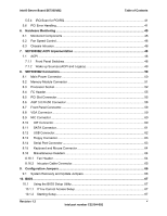
of Contents Intel® Server Board SE7505VB2 Table of Contents 1. Introduction ...13 2. SE7505VB2 Server Board Overview 14 2.1 Intel® Server Board SE7505VB2 Feature Set 14 3. Functional Architecture ...16 3.1 Processor and Memory Subsystem 16 3.1.1 Processor Support 16 3.1.2 Memory Subsystem 17 - Intel SE7505VB2 | Product Specification - Page 5
Intel® Server Board SE7505VB2 Table of Contents 5.5.4 IRQ Scan for PCIIRQ 41 5.6 PCI Error Handling...41 6. Hardware Monitoring ...45 6.1 Monitored Components 45 6.2 Fan Speed Control...46 6.3 Chassis Intrusion ...46 7. SE7505VB2 ACPI Implementation 48 7.1 ACPI ...48 7.1.1 Front Panel Switches - Intel SE7505VB2 | Product Specification - Page 6
90 10.3 Error Handling and Reporting 93 10.3.1 POST Error Beep Codes 93 10.3.2 BIOS Event Log...93 11. Absolute Maximum Ratings 94 12. Power Information...95 12.1 SE7505VB2 Server Board Power Budget 95 12.2 Power Supply Specifications 96 12.2.1 Power Timing ...96 12.2.2 Voltage Recovery Timing - Intel SE7505VB2 | Product Specification - Page 7
Intel® Server Board SE7505VB2 Table of Contents 13.3 Replacing the Back up Battery 102 14. Mechanical Specifications 104 Glossary...106 Reference Documents ...108 Index Error! Bookmark not defined. Revision 1.2 vii Intel part number C32194-002 - Intel SE7505VB2 | Product Specification - Page 8
47 Figure 10. System Recovery and Update Jumpers (J4J1 66 Figure 11. BIOS Recovery Jumper 92 Figure 12. Output Voltage Timing 97 Figure 13. Turn on / off Timing...98 Figure 14. Intel Server Board SE7505VB2 Mechanical Drawing 104 Figure 15. Board Photograph (Reference Only 105 viii Revision - Intel SE7505VB2 | Product Specification - Page 9
Intel® Server Board SE7505VB2 List of Tables List of Tables Table 1. Processor Support Matrix 16 Table 2. Memory Bank Labels ...20 Table 3. I2C Addresses for Memory Module SMB 21 Table 4. Supported DDRs...23 Table 5. ICH4 GPIO Usage Table 26 Table 6. Super I/O GPIO Usage Table 29 Table 7. PCI - Intel SE7505VB2 | Product Specification - Page 10
List of Tables Intel® Server Board SE7505VB2 Table 33. NIC2 (Gbit 10/100/1000) Connector Pin-out (J6A1 60 Table 34. ATA 40-pin Connector Pin-out (J3K2, J4K1 60 Table 35. SATA Connector Pin-out (J1H1 61 Table 36. SATA Connector Pin-out (J1H2 61 Table 37. USB Connectors Pin-out (J9A2 62 Table - Intel SE7505VB2 | Product Specification - Page 11
Intel® Server Board SE7505VB2 List of Tables Table 68. BIOS Event Log Error Messages 93 Table 69. Absolute Maximum Ratings 94 Table 70. The Board Power Budget 95 Table 71. The Board Power Supply Voltage Specification 96 Table 72. Voltage Timing Parameters 97 Table 73. Turn On / Off Timing 98 - Intel SE7505VB2 | Product Specification - Page 12
List of Tables Intel® Server Board SE7505VB2 xii Revision 1.2 Intel part number C32194-002 - Intel SE7505VB2 | Product Specification - Page 13
be made via the Specification Update published monthly from the date of product launch. Please refer to the Intel Server Board SE7505VB2 support website for any updates to this document: http://support.intel.com/support/motherboards/server/se7505vb2. Revision 1.2 13 Intel part number C32194-002 - Intel SE7505VB2 | Product Specification - Page 14
Set The Intel Server Board SE7505VB2 supports the following feature set: Processor/FSB support - Dual Intel Xeon processors with 512KB L2 cache using the 604-pin FCPGA processor package - 533 MHz FSB or 400 MHz FSB support - 4.2 GB/sec Bus Bandwidth - One version 9.1 compliant VRD to supply CPU core - Intel SE7505VB2 | Product Specification - Page 15
Intel® Server Board SE7505VB2 SE7505VB2 Server Board Overview Graphic AGP 3.0 Pro50 watt support - Support 2X, 4X and 8X AGP protocol - AGP Pro50 supported by additional power pins in 4X and 8X mode - Support 1.5V signal levels only - Maximum of 2.03 GB/sec Bus Bandwidth Three external Universal - Intel SE7505VB2 | Product Specification - Page 16
MCH can detect and correct single-bit errors (SBE), detect multiple-bit errors (MBE), and supports Intel® x4 Single Data Device Correction (Intel x4 SDDC) feature with x4 DIMMs. 3.1.1 Processor Support The Intel Server Board SE7505VB2 supports one or two processors in the 604-pin FCPGA package - Intel SE7505VB2 | Product Specification - Page 17
The Intel Server Board SE7505VB2 has a single VRD (Voltage Regulator Down) to support two processors. It is compliant with the VRM 9.1 specification and provides a maximum of 130 AMPs, which is capable of supporting the requirements for two Intel® Xeon™ processors. The board hardware and PMC (Power - Intel SE7505VB2 | Product Specification - Page 18
at 266MT/s. Only DIMMs tested and qualified by Intel or a designated memory test vendor are supported on this board. A list of qualified DIMMs is available at http://support.intel.com/support/motherboards/server/se7505vb2. Note that all DIMMs are supported by design, but only fully qualified DIMMs - Intel SE7505VB2 | Product Specification - Page 19
memory cooling duct specifically for the SE7505VB2 server board. Intel's testing has shown only 2GB and stacked 1GB (low profile) DIMMs are thermally at risk. If your specific design uses either of these size memory parts, contact Intel Customer Support and request the SE7505VB2 server board memory - Intel SE7505VB2 | Product Specification - Page 20
Functional Architecture Intel® Server Board SE7505VB2 Table 2. Memory Bank Labels Memory DIMM J9H1 (DIMM 1A), J9H2 (DIMM 1B) J9J1 (DIMM 2A), J9J2 (DIMM 2B) Bank 1 2 J9H1 J9H2 J9J1 J9J2 1A 1B 2A 2B Bank 1 Bank 2 Figure 3. Memory Bank Label Definition 20 Revision 1.2 Intel part number - Intel SE7505VB2 | Product Specification - Page 21
ratio of the ECC bits to data bits is the same as the previous example (16/128 vs. 8/64), the longer ECC word allows for a correction and detection algorithm that is more efficient. 3.2 The Intel® E7505 Chipset The Intel Server Board SE7505VB2 is designed around the Intel E7505 chipset. The chipset - Intel SE7505VB2 | Product Specification - Page 22
Functional Architecture Intel® Server Board SE7505VB2 ICH4: I/O Controller Hub 4. The ICH4 controller has several components. It provides the interface for a 32-bit/33-MHz PCI bus. The ICH4 can be both a master and a target on that PCI bus. The ICH4 also includes a USB 2.0 controller and an IDE - Intel SE7505VB2 | Product Specification - Page 23
Intel® Server Board SE7505VB2 Functional Architecture 3.2.1.1 DDR Configurations The DDR interface supports up to 8 GB of main memory and supports single- and doubledensity DIMMs. The DDR can be any industry-standard DDR. The following table shows the DDR DIMM technology supported. Table 4. - Intel SE7505VB2 | Product Specification - Page 24
Architecture Intel® Server Board SE7505VB2 3.2.2.1 AGP 8X Bus The AGP 8X bus features include the following: Single AGP device AGP interface asynchronously coupled to core AGP 3.0 specification compliant AGP 8X / 4X / 2X at 1.5V 0.8V and 1.5V AGP electrical. No 3.3V support Isochronous support - Intel SE7505VB2 | Product Specification - Page 25
connectors: An ATI Rage XL video controller with 3D/2D graphics accelerator Silicon Image 3112A dual channel SATA controller One Intel® 82550PM network controller Two expansion slots capable of supporting full length PCI add-in cards operating at 33 MHz 3.2.4.2 PCI Bus Master IDE Interface The - Intel SE7505VB2 | Product Specification - Page 26
Functional Architecture Intel® Server Board SE7505VB2 3.2.4.4 Compatibility Interrupt Control The ICH4 alternate functions, and thus all are not available. The following table lists the GPI and GPO pins used on the board and gives a brief description of their function. Table 5. ICH4 GPIO - Intel SE7505VB2 | Product Specification - Page 27
Intel® Server Board SE7505VB2 Functional Architecture Pin Name (Powe Well) Used As GPI12 (Resume) GPI13 (Resume) Overtemperature shutdown for CPU 1 18:23] 0) GPIO:R04h[24] = 0 GPIO:R0Ch[24] TTL Driver Output TTL Driver Output TTL Driver Output GPI GPI GPI GPI GPI GPI GPI GPO GPIO:R04h[25] = - Intel SE7505VB2 | Product Specification - Page 28
Functional Architecture Intel® Server Board SE7505VB2 Pin Name (Powe Well) GPIO37 / USBLED_F# (Core) GPIO38 / USBLED_G# (Core) GPIO39 / of the ICH4 is a power management controller. This is used to implement ACPI-compliant power management features. The baseboard does support sleep states S0, S1, - Intel SE7505VB2 | Product Specification - Page 29
Intel® Server Board SE7505VB2 Functional Architecture 3.3.1 GPIOs The sIO provides a number of general-purpose input/output pins that the baseboard utilizes. The following table identifies the pin and the signal name used in the schematic Pin 87) GPIO35 (Pin 64) Btn_dsabl# Blink_LED GPO CR2B - Intel SE7505VB2 | Product Specification - Page 30
Functional Architecture Intel® Server Board SE7505VB2 3.3.2.3 Floppy Disk power-on and power-off the system. 3.3.3 BIOS Flash The board incorporates an Intel® N82802AC (FWH8) flash memory component. The N82802AC is a high-performance 8-megabit memory component that provides 1024K x 8 of BIOS - Intel SE7505VB2 | Product Specification - Page 31
All buses on the Intel Server Board SE7505VB2 operate using synchronous clocks. Clock synthesizer/driver circuitry on the baseboard generates clock frequencies and voltage levels as required, including the following: 100 MHz at 3.3 V logic levels. For Processor 0, Processor 1, Debug Port and MCH - Intel SE7505VB2 | Product Specification - Page 32
Clock Generation and Distribution Intel® Server Board SE7505VB2 Figure 4. SE7505VB2 Clock Distribution Diagram 32 Revision 1.2 Intel part number C32194-002 - Intel SE7505VB2 | Product Specification - Page 33
5.1 PCI Subsystem The primary I/O bus for the server board SE7505VB2 is PCI, with three independent PCI bus segments. The PCI buses comply with the PCI Local Bus Specification, Rev 2.3. The P32-A bus segment is directed through the ICH4 while the two 64-bit segments, P64-B and P64-C, are directed - Intel SE7505VB2 | Product Specification - Page 34
Subsystem Intel® Server Board SE7505VB2 5.1.1.2 P32-A Arbitration P32-A supports six PCI devices: the ICH4 and five PCI bus masters (one NIC, one sATA RAID controller, two PCI slots and one ATI Rage XL video controller). All PCI masters must arbitrate for PCI access, using resources supplied by - Intel SE7505VB2 | Product Specification - Page 35
Intel® Server Board SE7505VB2 PCI I/O Subsystem 5.1.2.2 P64-B Arbitration P64-B supports three PCI masters: two PCI-X slots and the P64H2. All PCI masters must arbitrate for PCI access using resources supplied by the P64H2. The host bridge PCI interface (P64H2) arbitration lines REQx* and GNTx* - Intel SE7505VB2 | Product Specification - Page 36
Intel® Server Board SE7505VB2 The baseboard ships with the Silicon Image controller set to Base ATA mode. To switch the controller to RAID mode, a utility needs to be downloaded from the SE7505VB2 support SDRAM chip provides 8 MB of video memory. The SVGA subsystem supports a variety of modes, up to - Intel SE7505VB2 | Product Specification - Page 37
Intel® Server Board SE7505VB2 PCI I/O Subsystem 5.3.1 Video Modes The ATI Rage XL chip supports all standard IBM VGA modes. The following table shows the 2D/3D modes supported for both CRT and LCD. The table specifies the minimum memory requirement for various display resolution, refresh rates - Intel SE7505VB2 | Product Specification - Page 38
PCI I/O Subsystem Intel® Server Board SE7505VB2 5.3.3 Host Bus Interface The ATI Rage XL supports a PCI 33 MHz bus. The following diagram shows the signals for the PCI INTR# DEVSEL# REQ# GNT# REQ# GNT# Figure 5. Video Controller PCI Bus Interface 38 Revision 1.2 Intel part number C32194-002 - Intel SE7505VB2 | Product Specification - Page 39
Intel® Server Board SE7505VB2 PCI I/O Subsystem 5.4 Network Interface Controller (NIC) The server board SE7505VB2 supports one 10Base-T/100Base-TX network interface controller (NIC) based on the Intel 82550PM controller (NIC 1) and one gigabit network interface controller based on the Intel - Intel SE7505VB2 | Product Specification - Page 40
Intel® Server Board SE7505VB2 5.5 Interrupt Routing The board ICH4 I/O APIC exists on the I/O APIC bus with the processors. AGPA# Interrupt AGPB# VGA# sATA# NIC1# NIC2# P64H2-A# [P1/P2] P64-C Slot I/O APICs can also supply greater than 16 interrupt levels to the processor(s). This APIC bus - Intel SE7505VB2 | Product Specification - Page 41
Intel® Server Board SE7505VB2 PCI I/O Subsystem 5.5.2.1 Legacy Interrupt Sources The table below recommends the logical interrupt mapping of interrupt sources on the board ICH4 to the processors. 5.5.3 Serialized IRQ Support The SE7505VB2 server board supports a serialized interrupt delivery - Intel SE7505VB2 | Product Specification - Page 42
PCI I/O Subsystem Intel® Server Board SE7505VB2 IRQ0 IRQ1 IRQ2 IRQ3 IRQ4 IRQ5 IRQ6 IRQ7 IRQ8 IRQ9 IRQ10 IRQ11 IRQ12 IRQ13 IRQ14 IRQ15 INTERFACE P64H2 IOAPIC 2 MCH Hub-Link B INTR CPU1 CPU2 INTR Figure 6. Interrupt Routing Diagram (ICH4 Internal) 42 Revision 1.2 Intel part number C32194-002 - Intel SE7505VB2 | Product Specification - Page 43
Intel® Server Board SE7505VB2 PCI I/O Subsystem ICH4 Interrupt Routing Serialized IRQ Interface Timer Super I/O Keyboard Cascade Serial Port2/ISA Serial Port1/ISA ISA Floppy/ISA ISA RTC SCI/ISA ISA ISA Mouse/ISA Coprocessor Error P IDE/ISA Not Used AGPA# AGPB# / VGA# NIC1# sATA# - Intel SE7505VB2 | Product Specification - Page 44
PCI I/O Subsystem Intel® Server Board SE7505VB2 INT A INT B INT C INT D SLOT #1 SLOT #2 SLOT #3 SLOT #4 SLOT # ICH4 PIRQG# ICH4 PIRQE# ICH4 PIRQH# ICH4 PIRQF# ICH4 PIRQB# ICH4 PIRQA# NIC2# sATA# NIC1# P64H2-A# [P1/P2] AGPB# VGA# AGPA# Note: P1 is P64H2 PCI-bus B, P2 is P64H2 PCI - Intel SE7505VB2 | Product Specification - Page 45
The Intel Server Board SE7505VB2 has an integrated Winbond* Heceta chip that is responsible for hardware monitoring. The Winbond Heceta chip provides basic server hardware monitoring which alerts a system administrator if a hardware problem occurs on the board. The retail boxed board ships - Intel SE7505VB2 | Product Specification - Page 46
5Bh 4Eh 3Dh 39h CPU Fan Speed Limit 2766 RPM CPU Fan Count Limit 3Dh 6.3 Chassis Intrusion The SE7505VB2 server board supports a chassis security feature that detects if the chassis cover is removed. For the chassis intrusion circuit to function, the chassis' power supply must be connected to - Intel SE7505VB2 | Product Specification - Page 47
Intel® Server Board SE7505VB2 Hardware Monitoring Below is a diagram explaining what J5A2) NC Sys fan 1 (J5K3) Sys fan 2 (J5K2) Sys fan 4 (J5A2) Sys fan 3 (J8A2) CPU fan 2 (J8A3) CPU fan 1 (J7B1) VTIN1 VTIN2 Temperature Sensor 2 High Byte (Index 50h, Bank 1) VTIN3 Temperature Sensor 3 High Byte ( - Intel SE7505VB2 | Product Specification - Page 48
Intel® Server Board SE7505VB2 7. SE7505VB2 ACPI Implementation 7.1 ACPI An ACPI-aware operating system generates an SMI to request that the system be switched into ACPI mode. The BIOS responds to enable ACPI mode. The system automatically returns to legacy mode upon hard reset or power (Processor - Intel SE7505VB2 | Product Specification - Page 49
Intel® Server Board SE7505VB2 SE7505VB2 ACPI Implementation The power button input (SW2#) provides PWRBTN_IN signal to the sIO. The power button input behaves differently depending on whether or not the operating system supports ACPI. Power Button Off to On: The sIO may be configured to generate - Intel SE7505VB2 | Product Specification - Page 50
SE7505VB2 Connectors Intel® Server Board SE7505VB2 8. SE7505VB2 Connectors 8.1 Main Power Connector The main power supply SCL SDA PWR_Alert# GNDsens 3.3Vsens Color Green Yellow Red Black Orange Table 22. Auxiliary CPU Power Connector Pin-out (J9K1) Signal +12ENG +12ENG +12ENG +12ENG Pin 5 6 7 - Intel SE7505VB2 | Product Specification - Page 51
Intel® Server Board SE7505VB2 SE7505VB2 Connectors 8.2 Memory Module Connector The board has four DDR266 DIMM connectors and supports registered ECC DDR modules (Rev 1.0). Table 23. DIMM Connectors (J9H1, J9J1, J9H2, J9J2) Pin Front Pin Front Pin 1 VREF 32 A5 62 2 DQ0 33 DQ24 - Intel SE7505VB2 | Product Specification - Page 52
SE7505VB2 Connectors Intel® Server Board SE7505VB2 8.3 Processor Socket The board has two Socket 604 processor sockets. The following table provides the processor socket pin numbers and pin names: Table 24. Socket 604 Processor Socket Pin-out (U8C1, U5C1) Pin No Pin Name A1 Reserved A2 VCC - Intel SE7505VB2 | Product Specification - Page 53
Intel® Server Board SE7505VB2 SE7505VB2 Connectors Pin No Pin Name B9 VSS B10 A21# B11 A22# B12 VCC B13 A13# B14 A12# B15 VSS B16 A11# VSS AD22 DBI1# G31 VSS P26 VCC Y26 D0# AD23 VSS H1 VCC P27 VSS Y27 Reserved AD24 D21# Revision 1.2 53 Intel part number C32194-002 - Intel SE7505VB2 | Product Specification - Page 54
SE7505VB2 Connectors Intel® Server Board SE7505VB2 Pin No Pin Name Pin No Pin Name Pin are "Reserved " pins on the Intel® Xeon™ processor. In systems utilizing the Intel® Xeon™ processor, the system designer must terminate these signals to the processor VCC. 2. Baseboards treating AA3 and AB3 - Intel SE7505VB2 | Product Specification - Page 55
Intel® Server Board SE7505VB2 SE7505VB2 Connectors 8.4 I2C Header Table 25. SCSI HDD Header Pin-out (J3K2, J4K1) Pin Signal Name Description 1 3VSB SDA Data Line 2 GND 3 3VSB SCL Clock Line 4 +5VSB Power Line 8.5 PCI Slot Connector There are three PCI buses implemented on the - Intel SE7505VB2 | Product Specification - Page 56
SE7505VB2 Connectors Intel® Server Board SE7505VB2 Table 27. P64-B 3.3V 64-bit/100-MHz PCI-X Slot Pin-out (J2B1 ACK64# REQ64# 61 +5V +5V 62 +5V +5V CONNECTOR KEY CONNECTOR KEY 63 Reserved Ground 64 Ground C/BE[7]# 65 C/BE[6]# C/BE[5]# 66 C/BE[4]# +3.3V (I/O) 67 Ground PAR64 68 AD - Intel SE7505VB2 | Product Specification - Page 57
Intel® Server Board SE7505VB2 44 C/BE[1]# 45 AD[14] 46 Ground 47 AD[12] 48 AD[10] AD[15] +3.3V AD[13] AD[11] Ground 90 AD[33] 91 Ground 92 Reserved 93 Reserved 94 Ground SE7505VB2 Connectors Ground AD[32] Reserved Ground Reserved Table 28. P64-C 3.3V 64-bit/66-MHz PCI Slot Pin-out (J1B1) Pin - Intel SE7505VB2 | Product Specification - Page 58
SE7505VB2 Connectors Intel® Server Board SE7505VB2 KEY 64 Vddq1 specification. 2. TYPEDET# and GC_DET# should be both grounded by AGP3.0 and Universal AGP3.0 cards.These will be pulled up to the appropriate voltage by the motherboard. 3. IDSEL# is not a pin on the AGP3.0 connector. AGP3.0 graphics - Intel SE7505VB2 | Product Specification - Page 59
Intel® Server Board SE7505VB2 SE7505VB2 Connectors 8.7 Front Panel Connector A standard SSI 34-pin header is provided to support a system front panel. The header contains reset, NMI, power control buttons, and LED indicators. The following table details the pin-out of this header. Table 30. Front - Intel SE7505VB2 | Product Specification - Page 60
SE7505VB2 Connectors Intel® Server Board SE7505VB2 8.9 NIC Connector The server board SE7505VB2 supports two 12 13 14 Signal Name GND P3V_STAY NIC_100_L NIC_ACT_L LK_STATUS2_L GND GND 8.10 IDE Connector The board provides two 40-pin ATA-100 IDE connectors Table 34. ATA 40-pin Connector Pin-out - Intel SE7505VB2 | Product Specification - Page 61
Intel® Server Board SE7505VB2 Pin Signal Name 23 IDE_IOW# 25 IDE_IOR# 27 IDE_IORDY 29 IDE_DMAACK# 31 IRQ_IDE 33 IDE_A1 35 IDE_A0 37 IDE_DCS0# 39 IDE_HD_ACT# SE7505VB2 . The pin-out for these two connectors is listed below. Table 35. SATA Connector Pin-out (J1H1) Pin Signal Name 1 - Intel SE7505VB2 | Product Specification - Page 62
SE7505VB2 Connectors Intel® Server Board SE7505VB2 8.12 USB Connector The following table provides the pin- ) 12 GND 13 GND 14 GND 15 GND 16 GND A header on the server board provides an option to support one additional USB connector. The pin-out of the header is detailed in the following - Intel SE7505VB2 | Product Specification - Page 63
Intel® Server Board SE7505VB2 SE7505VB2 Connectors 8.13 Floppy Connector The board Server Board SE7505VB2. A standard, external DB9 serial connector is located on the back edge of the baseboard to supply a Serial A interface A Serial B port is provided through a 9-pin header on the server board - Intel SE7505VB2 | Product Specification - Page 64
SE7505VB2 Connectors Intel® Server Board SE7505VB2 Table 41. 9-pin Header Serial B Port Pin-out (J1J2) Signal Power 3 Fan Tach Type Power Power Out Description GROUND is the power supply ground Fan Power FAN_TACH signal is connected to the sIO to monitor the FAN speed. 64 Revision 1.2 Intel - Intel SE7505VB2 | Product Specification - Page 65
Intel® Server Board SE7505VB2 SE7505VB2 Connectors 8.16.2 Intrusion Cable Connector Table 44. Intrusion Cable Connector Pin-Out Pin Signal Name 1 Intruder_FET_L 2 P3V_STBY Revision 1.2 65 Intel part number C32194-002 - Intel SE7505VB2 | Product Specification - Page 66
section describes configuration jumper options on the Intel Server Board SE7505VB2. 9.1 System Recovery and Update Jumpers A 10-pin block (J4J1 operation. The BIOS bootblock write protect jumper on pins 7-8 should be left on these pins at all times except when instructed by the BIOS release notes to - Intel SE7505VB2 | Product Specification - Page 67
Server Board SE7505VB2 BIOS 10. BIOS 10.1 Using the BIOS Setup Utility This section describes the BIOS Setup Utility options. For more details on the BIOS and its functionality, contact your Intel field representative to obtain the Intel Server Board SE7505VB2 BIOS External Product Specification - Intel SE7505VB2 | Product Specification - Page 68
BIOS Intel® Server Board SE7505VB2 Table 46. Keyboard Commands Press - Intel SE7505VB2 | Product Specification - Page 69
Intel® Server Board SE7505VB2 BIOS Table 47 describes the on-screen options you will see in BIOS Setup and what they mean. Table 47. On-Screen Options When you see this: On screen, an option is shown but you cannot select it - Intel SE7505VB2 | Product Specification - Page 70
BIOS Intel® Server Board SE7505VB2 10.1.5 Main Menu To access this menu, select Main on the menu bar at the top of the screen. Main Advanced Primary Master Primary Slave Secondary Master Secondary Slave Security Power Boot System Exit Table 49 lists the options available on the Main - Intel SE7505VB2 | Product Specification - Page 71
Intel® Server Board SE7505VB2 BIOS 10.1.5.1 Primary/Secondary, Master/Slave Submenus To access this submenu, select Main on the menu bar at the top of the screen and then the - Intel SE7505VB2 | Product Specification - Page 72
BIOS Intel® Server Board SE7505VB2 10.1.6 Advanced Menu To access this menu, select Advanced on the menu bar at the top of the screen. Main Advanced Security I/O Device Configuration On Board Devices PCI Configuration Server Menu Console Redirection Event Logging Hardware Monitor Power Boot - Intel SE7505VB2 | Product Specification - Page 73
Intel® Server Board SE7505VB2 BIOS Feature Reset Configuration Data Choices • No (default) • Yes Large Disk Access Mode • Other • DOS (default) PS/2 Mouse • Disabled • Enabled • Auto Detect (default) Summary Screen Legacy USB Support Hyper-Threading • Disabled • Enabled (default) • Disabled - Intel SE7505VB2 | Product Specification - Page 74
BIOS Intel® Server Board SE7505VB2 Table 52 lists the options available through the I/O Device Configuration submenu. This submenu configures the I/O ports on the board. Table 52. I/O Device Configuration Submenu Feature Serial port A Base I/O Address (This feature is present only when Serial - Intel SE7505VB2 | Product Specification - Page 75
Intel® Server Board SE7505VB2 BIOS Depending on the Mode is selected above, the parallel port configuration options are different: Output only option Description Configure using these options [Disabled] No Configuration [Enabled] User Configuration Revision 1.2 75 Intel part number C32194-002 - Intel SE7505VB2 | Product Specification - Page 76
BIOS Intel® Server Board SE7505VB2 10.1.6.2 On Board Device Submenu To access this submenu, select Advanced on the menu bar at the top of the screen and then select On Board Device. Main Advanced Security I/O Device Configuration On Board Device PCI Configuration Server Menu Console - Intel SE7505VB2 | Product Specification - Page 77
Intel® Server Board SE7505VB2 BIOS 10.1.6.3 PCI Configuration Submenu To access this submenu, select Advanced on the menu bar at the top of the screen and then PCI Configuration. Main Advanced Security I/O Device Configuration On Board Device PCI Configuration Onboard Serial ATA Onboard NICs - Intel SE7505VB2 | Product Specification - Page 78
BIOS Intel® Server Board SE7505VB2 Table 55 lists showing which mode the SATA controller is in: Base ATA or RAID Table 56 lists the options available in • Disabled Description Enables/Disables add-in card option ROM expansion by slot. 10.1.6.4 Server Menu Submenu To access this submenu, - Intel SE7505VB2 | Product Specification - Page 79
Intel® Server Board SE7505VB2 Main Advanced Security I/O Device Configuration On Board Device PCI Configuration Server Menu Console Redirection Event Logging Hardware Monitor Power Boot BIOS System Exit Table 58 lists the options available through the Server Menu submenu. This submenu allows - Intel SE7505VB2 | Product Specification - Page 80
BIOS Intel® Server Board SE7505VB2 Table 59 lists the options available through the Control Console Connection Continue C.R. after POST Table 59. Console Redirection Submenu Choices • Disabled (default) • On-board COM A • On-board COM B • 300 • 1200 • 2400 • 9600 • 19.2k (default) • 38.4k • - Intel SE7505VB2 | Product Specification - Page 81
Intel® Server Board SE7505VB2 BIOS 10.1.6.6 Event Logging Submenu To access this submenu, select Advanced on the menu bar at the top of the screen and then Event Logging. Main Advanced Security I/O Device Configuration On Board Device PCI Configuration Server Menu Console Redirection Event - Intel SE7505VB2 | Product Specification - Page 82
BIOS Intel® Server Board SE7505VB2 10.1.6.7 Hardware Monitor Submenu To access this submenu, select Advanced on the menu bar at the top of the screen and then Hardware Monitor. Main Advanced Security I/O Device Configuration On Board Device PCI Configuration Server Menu Console Redirection - Intel SE7505VB2 | Product Specification - Page 83
Intel® Server Board SE7505VB2 BIOS 10.1.7 Security Menu To access this menu, select Security on the menu bar at the top of the screen. Main Advanced Security Power Boot System Exit Table 62 lists the options available on the Security menu. Enabling the Supervisor Password field requires a - Intel SE7505VB2 | Product Specification - Page 84
BIOS Intel® Server Board SE7505VB2 10.1.8 Power Menu To access this menu, select Power on the menu bar at the top of the screen Main Advanced Security Power Boot System Exit Table 63 lists the options available on the Power menu. This menu is designed to configure various aspects of the - Intel SE7505VB2 | Product Specification - Page 85
Intel® Server Board SE7505VB2 BIOS 10.1.9 Boot Menu To access this menu, select Boot on the menu bar at the top of the screen Main Advanced Security Power Boot System Exit Table 64 lists a BIOS Boot Specification (BBS)-compliant SCSI CD-ROM. • Network Boot: If the network card ROM - Intel SE7505VB2 | Product Specification - Page 86
BIOS Intel® Server Board SE7505VB2 10.1.10 System Menu To access this menu, select System on the menu bar at the top of the screen Main Advanced Security Power Boot System Exit Table 65 lists the options available on the System menu. This menu displays information on vendor, processor, - Intel SE7505VB2 | Product Specification - Page 87
Intel® Server Board SE7505VB2 BIOS Feature Peripherals BIOS Choices Description Provides the port connectors for onboard designators. None of these can be modified in user mode Port On Board Connector Designator Port On Board Power Boot System Exit Table 66 lists the - Intel SE7505VB2 | Product Specification - Page 88
file and the PHLASH.EXE utility from the Intel Customer Support Web site: http://support.intel.com/support/motherboards/server/SE7505VB2 Note: Please review the instructions distributed with the upgrade utility before attempting a BIOS upgrade. Review also any release notes that accompany the new - Intel SE7505VB2 | Product Specification - Page 89
the files you need to upgrade the BIOS. 1. Download the BIOS image file to a temporary folder on your hard drive. The image is available from http://support.intel.com/support/motherboards/server/SE7505VB2 2. Execute the BIOS.EXE file to extract the update files from the image file. 3. Insert the - Intel SE7505VB2 | Product Specification - Page 90
BIOS Intel® Server Board SE7505VB2 4. If you selected option 2, to manually update the BIOS or to update the flash memory, you can either select "Update Flash Memory From a File" or "Update System BIOS": Update Flash Memory From a File: When prompted for a file name, type BIOS.wph and press Enter. - Intel SE7505VB2 | Product Specification - Page 91
Intel® Server Board SE7505VB2 BIOS 10.2.3.1 Creating the Crisis Recovery Diskette Note: The crisis recovery diskette must be created on a Windows 98, Windows 2000, or Windows XP system. Use the following steps to create the diskette: 1. Create an empty folder at the Windows workstation. 2. - Intel SE7505VB2 | Product Specification - Page 92
BIOS Intel® Server Board SE7505VB2 10.2.3.2 Manually Recovering the BIOS A BIOS recovery can also be manually initiated. This option would be used only when the BIOS is corrupt, but the ROM checksum error does not occur during POST. To manually initiate a BIOS recovery, use the following steps: - Intel SE7505VB2 | Product Specification - Page 93
Intel® Server Board SE7505VB2 BIOS 10.3 Error Handling and Reporting 10.3.1 POST Error Beep Codes Table 67. POST Error Beep Codes Beeps 4-3-1-2 4-3-1-3 4-3-1-4 4-3-3-1 4-3-3-2 4-3-3-3 4-3-3-4 4-3-4-1 4-3-4-2 4-3-4-3 1-3-4-3 Reason No memory DIMM(s) Memory type is mismatch No DIMM Pair(s) in - Intel SE7505VB2 | Product Specification - Page 94
Absolute Maximum Ratings Intel® Server Board SE7505VB2 11. Absolute Maximum Ratings Operating the board at conditions beyond design must provide proper airflow to avoid exceeding the processor maximum case temperature. 2. VDD means supply voltage for the device 11.1 Mean Time Between Failures - Intel SE7505VB2 | Product Specification - Page 95
Intel® Server Board SE7505VB2 Power Information 12. Power Information 12.1 SE7505VB2 Server Board Power Budget The following table shows the power consumed on each supply line for the SE7505VB2 baseboard that is configured with two processors (each 68W max) and Intel Xeon processors 631 Memory - Intel SE7505VB2 | Product Specification - Page 96
90 75% 7.43 CPU Fan 2 4.80 75% 3.60 Board Level output current 0.23 0.27 0.30 0.01 1.98 0.48 Intel® Server Board SE7505VB2 0.08 0.09 0.15 0.39 0.75 0.50 0.08 0.06 13.09 0.181 0.216 0.240 0.010 1.49 0.36 11.585 18.51 0.054 0.059 0.121 0.250 0.484 12.2 Power Supply Specifications This section - Intel SE7505VB2 | Product Specification - Page 97
Intel® Server Board SE7505VB2 Vout 10% Vout V1 V2 V3 Power Information Tvout rise Tvout_on Tvout_off Figure 12. Output Voltage Timing The following tables show the timing requirements for a single power supply being turned on and off via the AC input, with PSON held low and the PSON signal, - Intel SE7505VB2 | Product Specification - Page 98
Power Information AC Input Vout TAC_on_delay Tsb_on_delay PWOK Tpwok_on Tpwok_holdup 5VSB PSON Tsb_vout Intel® Server Board SE7505VB2 Tvout_holdup Tpwok_off Tpwok_low Tsb_on_delay Tpwok_on Tpwok_off Tpson_pwok Tpson_on_delay AC turn on/off cycle PSON turn on/off cycle Figure 13. Turn - Intel SE7505VB2 | Product Specification - Page 99
Intel® Server Board SE7505VB2 Power Information 12.2.2 Voltage Recovery Timing Specifications The power supply must conform to the following specifications for voltage recovery timing under load changes: Voltage shall remain within +/- 5% of the nominal set voltage on the +5 V, +12 V, 3.3 V, 5 - Intel SE7505VB2 | Product Specification - Page 100
Product Regulatory Compliance Intel® Server Board SE7505VB2 13. Product Regulatory Compliance 13.1.1 Product Safety Compliance The Intel Server Board SE7505VB2 complies with the following safety requirements: UL60 1950 - CSA60 950 (USA/Canada) EN 60 950 (CENELEC Europe) IEC60 950 ( - Intel SE7505VB2 | Product Specification - Page 101
Intel® Server Board SE7505VB2 Product Regulatory Compliance 13.1.4 Other Product Mandatory Regulations manufacturer. All Fans shall have the minimum certifications: UL and TUV or VDE All external power connectors shall have current limiting devices that have UL and TUV or VDE certifications and - Intel SE7505VB2 | Product Specification - Page 102
on the server board powers the real time clock (RTC) for up to 10 years in the absence of power. When the battery starts to weaken, it loses voltage, and the server settings stored in CMOS RAM in the RTC (for example, the date and time) may be wrong. Contact your customer service representative or - Intel SE7505VB2 | Product Specification - Page 103
Intel® Server Board SE7505VB2 Product Regulatory Compliance ADVARSEL! Lithiumbatteri - Eksplosionsfare ved fejlagtig håndtering. Udskiftning må kun laitevalmistajan suosittelemaan tyyppiin. Hävitä käytetty paristo valmistajan ohjeiden mukaisesti. Revision 1.2 103 Intel part number C32194-002 - Intel SE7505VB2 | Product Specification - Page 104
Mechanical Specifications Intel® Server Board SE7505VB2 14. Mechanical Specifications The following figure shows the server board mechanical drawing. Figure 14. Intel Server Board SE7505VB2 Mechanical Drawing 104 Revision 1.2 Intel part number C32194-002 - Intel SE7505VB2 | Product Specification - Page 105
Intel® Server Board SE7505VB2 Mechanical Specifications Figure 15. Board Photograph (Reference Only) Revision 1.2 105 Intel part number C32194-002 - Intel SE7505VB2 | Product Specification - Page 106
Mechanical Specifications Intel® Server Board SE7505VB2 Glossary This appendix contains important terms used in the preceding chapters. For ease of use, numeric entries are listed first (e.g., "82460GX") with alpha entries following (e.g., "AGP 8x"). Acronyms are then entered in their respective - Intel SE7505VB2 | Product Specification - Page 107
Intel® Server Board SE7505VB2 Mechanical Specifications P64H2 PBGA POST RAM RISC ROM SDRAM SMI TBD UART USB Word Intel® PCI-X 64-bit Hub 2 Pin Ball Grid Array Power-on Self Test Random Access Memory Reduced instruction set computing Read Only Memory Synchronous Dynamic RAM Server management - Intel SE7505VB2 | Product Specification - Page 108
ATI Rage XL Graphics Controller Specifications, Technical Reference Manual, Rev 2.01 VRM 9.1 Specification I2C Bus Specification USB 2.0 Intel® Server Board SE7505VB2 BIOS EPS2 SSI-EEB 3.0 Windows Logo/SDG 3.0 ACPI 1.0b SMBIOS 2.3.1 PC2001 (only if WS cert) AGP 3.0 Spec AGP Design Guide Rev 1.5 AGP
-
 1
1 -
 2
2 -
 3
3 -
 4
4 -
 5
5 -
 6
6 -
 7
7 -
8
-
9
-
10
-
11
-
12
-
13
-
14
-
15
-
16
-
17
-
18
-
19
-
20
-
21
-
22
-
23
-
24
-
25
-
26
-
27
-
28
-
29
-
30
-
31
-
32
-
33
-
34
-
35
-
36
-
37
-
38
-
39
-
40
-
41
-
42
-
43
-
44
-
45
-
46
-
47
-
48
-
49
-
50
-
51
-
52
-
53
-
54
-
55
-
56
-
57
-
58
-
59
-
60
-
61
-
62
-
63
-
64
-
65
-
66
-
67
-
68
-
69
-
70
-
71
-
72
-
73
-
74
-
75
-
76
-
77
-
78
-
79
-
80
-
81
-
82
-
83
-
84
-
85
-
86
-
87
-
88
-
89
-
90
-
91
-
92
-
93
-
94
-
95
-
96
-
97
-
98
-
99
-
100
-
101
-
102
-
103
-
104
-
105
-
106
-
107
-
108
 |
 |
Intel® Server Board
SE7505VB2
Technical Product Specification
Intel part number C32194-002
Revision 1.2
April 2004
Enterprise Platforms and Services Marketing