Intel SE7505VB2 Product Specification - Page 58
AGP 3.0 Pro50 Connector, SE7505VB2 Connectors, Intel® Server Board SE7505VB2
 |
View all Intel SE7505VB2 manuals
Add to My Manuals
Save this manual to your list of manuals |
Page 58 highlights
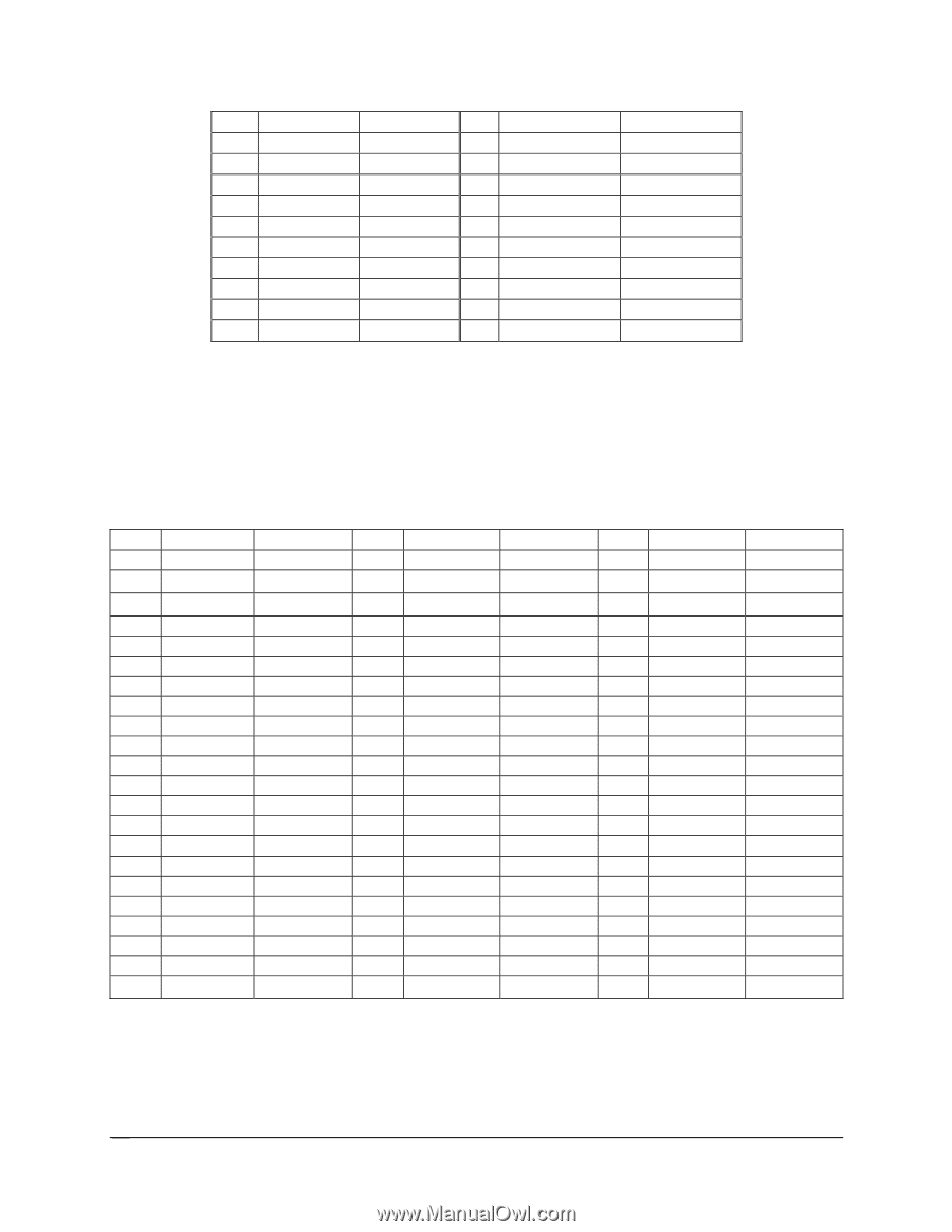
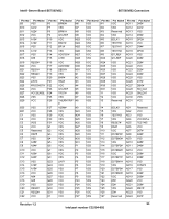
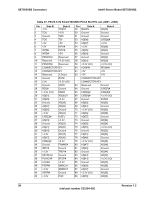
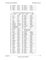
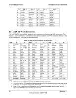
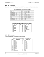
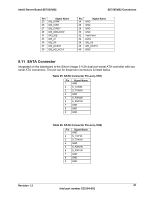
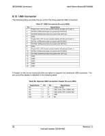
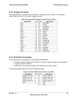
SE7505VB2 Connectors Intel® Server Board SE7505VB2 Pin 39 40 41 42 43 44 45 46 47 48 Side B LOCK# PERR# +3.3V SERR# +3.3V C/BE[1]# AD[14] Ground AD[12] AD[10] Side A +3.3V Reserved* Reserved* Ground PAR AD[15] +3.3V AD[13] AD[11] Ground Pin Side B 85 Ground 86 AD[39] 87 AD[37] 88 +3.3V (I/O) 89 AD[35] 90 AD[33] 91 Ground 92 Reserved 93 Reserved 94 Ground Side A AD[40] AD[38] Ground AD[36] AD[34] Ground AD[32] Reserved Ground Reserved 8.6 AGP 3.0 Pro50 Connector The AGP 3.0 Pro connector is designed as an extension to the existing AGP connectors. The standard AGP connector is extended on each end to build the AGP Pro connector. Below is the pin-out of the AGP connector on the baseboard. Table 29. AGP 3.0 Pro Connector Pin-out (J4C1) Pin# B A Pin# B A Pin# B A 1 OVRCNT# 12V 23 GND GND 45 KEY KEY 2 5.0V TYPEDET# 2 24 3.3VAUX Reserved 1 46 DEVSEL TRDY 3 5.0V GC_DET# 2 25 VCC3.3 VCC3.3 47 Vddq1.5 STOP 4 USB+ USB- 26 AD31 AD30 48 PERR PME# 5 GND GND 27 AD29 AD28 49 GND GND 6 INTB# INTA# 28 VCC3.3 VCC3.3 50 SERR PAR 7 CLK RST# 29 AD27 AD26 51 C#/BE1 AD15 8 REQ GNT 30 AD25 AD24 52 Vddq1.5 Vddq1.5 9 VCC3.3 VCC3.3 31 GND GND 53 AD14 AD13 10 ST0 ST1 32 AD_STBF1 AD_STBS1 54 AD12 AD11 11 ST2 MB_DET# 33 AD23 C#/BE3 55 GND GND 12 RBF DBI_HI 34 Vddq1.5 Vddq1.5 56 AD10 AD9 13 GND GND 35 AD21 AD22 57 AD8 C#/BE0 14 DBI_LO WBF 36 AD19 AD20 58 Vddq1.5 Vddq1.5 15 SBA0# SBA1# 37 GND GND 59 AD_STBF0 AD_STBS0 16 VCC3.3 VCC3.3 38 AD17 AD18 60 AD7 AD6 17 SBA2# SBA3# 39 C#/BE2 AD16 61 GND GND 18 SB_STBF SB_STBS 40 Vddq1.5 Vddq1.5 62 AD5 AD4 19 GND GND 41 IRDY FRAME 63 AD3 AD2 20 SBA4# SBA5# 42 KEY KEY 64 Vddq1.5 Vddq1.5 21 SBA6# SBA7# 43 KEY KEY 65 AD1 AD0 22 Reserved 1 Reserved 1 44 KEY KEY 66 AGPVrefcg AGPVrefgc Notes: 1. Reserved pins are only for future use by the AGP3.0 interface specification. 2. TYPEDET# and GC_DET# should be both grounded by AGP3.0 and Universal AGP3.0 cards.These will be pulled up to the appropriate voltage by the motherboard. 3. IDSEL# is not a pin on the AGP3.0 connector. AGP3.0 graphics components should connect the AD16 signal to the IDSEL# function internal to the component. 58 Revision 1.2 Intel part number C32194-002
-
 1
1 -
2
-
3
-
4
-
5
-
6
-
7
-
8
-
9
-
10
-
11
-
12
-
13
-
14
-
15
-
16
-
17
-
18
-
19
-
20
-
21
-
22
-
23
-
24
-
25
-
26
-
27
-
28
-
29
-
30
-
31
-
32
-
33
-
34
-
35
-
36
-
37
-
38
-
39
-
40
-
41
-
42
-
43
-
44
-
45
-
46
-
47
-
48
-
49
-
50
-
51
-
52
-
 53
53 -
 54
54 -
 55
55 -
 56
56 -
 57
57 -
 58
58 -
 59
59 -
 60
60 -
 61
61 -
 62
62 -
 63
63 -
64
-
65
-
66
-
67
-
68
-
69
-
70
-
71
-
72
-
73
-
74
-
75
-
76
-
77
-
78
-
79
-
80
-
81
-
82
-
83
-
84
-
85
-
86
-
87
-
88
-
89
-
90
-
91
-
92
-
93
-
94
-
95
-
96
-
97
-
98
-
99
-
100
-
101
-
102
-
103
-
104
-
105
-
106
-
107
-
108
 |
 |