Intel SE7505VB2 Product Specification - Page 62
USB Connector, Table 38. Optional USB Connection Header Pin-out J5K1
 |
View all Intel SE7505VB2 manuals
Add to My Manuals
Save this manual to your list of manuals |
Page 62 highlights
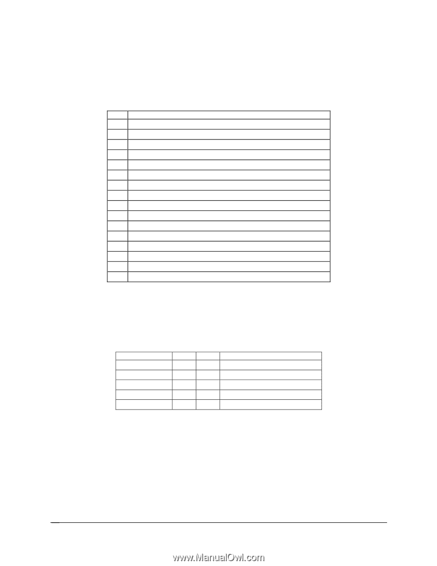
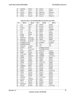
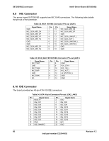
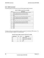
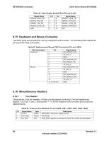
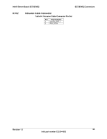
SE7505VB2 Connectors Intel® Server Board SE7505VB2 8.12 USB Connector The following table provides the pin-out for the three external USB connectors. Table 37. USB Connectors Pin-out (J9A2) Pin Signal Name 1 Fused VCC (+5V /w over current monitor of both port 0 and 1) 2 DATAL0 (Differential data line paired with DATAH0) 3 DATAH0 (Differential data line paired with DATAL0) 4 GND 5 Fused VCC (+5V /w over current monitor of both port 0 and 1) 6 DATAL1 (Differential data line paired with DATAH1) 7 DATAH1 (Differential data line paired with DATAL1) 8 GND 9 Fused VCC (+5V /w over current monitor of both port 0 and 1) 10 DATAL2 (Differential data line paired with DATAH2) 11 DATAH2 (Differential data line paired with DATAL2) 12 GND 13 GND 14 GND 15 GND 16 GND A header on the server board provides an option to support one additional USB connector. The pin-out of the header is detailed in the following table. Table 38. Optional USB Connection Header Pin-out (J5K1) Signal Name NC NC NC NC Key Pin 1 3 5 7 9 Pin 2 4 6 8 10 Signal Name USB2_VBUS2 USB_ICH4_P3N_CONN_IND USB_ICH4_P3P_CONN_IND GND NC 62 Revision 1.2 Intel part number C32194-002
-
 1
1 -
2
-
3
-
4
-
5
-
6
-
7
-
8
-
9
-
10
-
11
-
12
-
13
-
14
-
15
-
16
-
17
-
18
-
19
-
20
-
21
-
22
-
23
-
24
-
25
-
26
-
27
-
28
-
29
-
30
-
31
-
32
-
33
-
34
-
35
-
36
-
37
-
38
-
39
-
40
-
41
-
42
-
43
-
44
-
45
-
46
-
47
-
48
-
49
-
50
-
51
-
52
-
53
-
54
-
55
-
56
-
 57
57 -
 58
58 -
 59
59 -
 60
60 -
 61
61 -
 62
62 -
 63
63 -
 64
64 -
 65
65 -
 66
66 -
 67
67 -
68
-
69
-
70
-
71
-
72
-
73
-
74
-
75
-
76
-
77
-
78
-
79
-
80
-
81
-
82
-
83
-
84
-
85
-
86
-
87
-
88
-
89
-
90
-
91
-
92
-
93
-
94
-
95
-
96
-
97
-
98
-
99
-
100
-
101
-
102
-
103
-
104
-
105
-
106
-
107
-
108
 |
 |