Intel SE7505VB2 Product Specification - Page 9

List of Tables - supported processors

Page 9 highlights

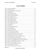
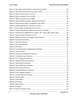
Intel® Server Board SE7505VB2 List of Tables List of Tables Table 1. Processor Support Matrix 16 Table 2. Memory Bank Labels ...20 Table 3. I2C Addresses for Memory Module SMB 21 Table 4. Supported DDRs...23 Table 5. ICH4 GPIO Usage Table 26 Table 6. Super I/O GPIO Usage Table 29 Table 7. PCI Bus Segment Characteristics 33 Table 8. P32-A Configuration IDs 33 Table 9. P32-A Arbitration Connections 34 Table 10. P64-B Configuration IDs 34 Table 11. P64-C Configuration IDs 34 Table 12. P64-B Arbitration Connections 35 Table 13. P64-C Arbitration Connections 35 Table 14. sATA RAID Level ...36 Table 15. Video Modes ...37 Table 16. PCI Interrupt Routing/Sharing 40 Table 17. Interrupt Definitions...41 Table 18. Monitored Components 45 Table 19. Supported Wake Events 49 Table 20. Power Connector Pin-out (J9B1 50 Table 21. Auxiliary Signal Connector (J7K1 50 Table 22. Auxiliary CPU Power Connector Pin-out (J9K1 50 Table 23. DIMM Connectors (J9H1, J9J1, J9H2, J9J2 51 Table 24. Socket 604 Processor Socket Pin-out (U8C1, U5C1 52 Table 25. SCSI HDD Header Pin-out (J3K2, J4K1 55 Table 26. P32-A 5V 32-bit/33-MHz PCI Slot Pin-out (J4B1, J3B1 55 Table 27. P64-B 3.3V 64-bit/100-MHz PCI-X Slot Pin-out (J2B1, J2B2 56 Table 28. P64-C 3.3V 64-bit/66-MHz PCI Slot Pin-out (J1B1 57 Table 29. AGP 3.0 Pro Connector Pin-out (J4C1 58 Table 30. Front Panel 34-Pin Header Pin-out (J1J1 59 Table 31. VGA Connector Pin-out (J7A1 59 Table 32. NIC1 (10/100) Connector Pin-out (J5A1 60 Revision 1.2 ix Intel part number C32194-002

  • 1
  • 2
  • 3
  • 4
  • 5
  • 6
  • 7
  • 8
  • 9
  • 10
  • 11
  • 12
  • 13
  • 14
  • 15
  • 16
  • 17
  • 18
  • 19
  • 20
  • 21
  • 22
  • 23
  • 24
  • 25
  • 26
  • 27
  • 28
  • 29
  • 30
  • 31
  • 32
  • 33
  • 34
  • 35
  • 36
  • 37
  • 38
  • 39
  • 40
  • 41
  • 42
  • 43
  • 44
  • 45
  • 46
  • 47
  • 48
  • 49
  • 50
  • 51
  • 52
  • 53
  • 54
  • 55
  • 56
  • 57
  • 58
  • 59
  • 60
  • 61
  • 62
  • 63
  • 64
  • 65
  • 66
  • 67
  • 68
  • 69
  • 70
  • 71
  • 72
  • 73
  • 74
  • 75
  • 76
  • 77
  • 78
  • 79
  • 80
  • 81
  • 82
  • 83
  • 84
  • 85
  • 86
  • 87
  • 88
  • 89
  • 90
  • 91
  • 92
  • 93
  • 94
  • 95
  • 96
  • 97
  • 98
  • 99
  • 100
  • 101
  • 102
  • 103
  • 104
  • 105
  • 106
  • 107
  • 108

IntelĀ® Server Board SE7505VB2
List of Tables
List of Tables
Table 1. Processor Support Matrix
.............................................................................................
16
Table 2. Memory Bank Labels
....................................................................................................
20
Table 3. I
2
C Addresses for Memory Module SMB
......................................................................
21
Table 4. Supported DDRs
...........................................................................................................
23
Table 5. ICH4 GPIO Usage Table
..............................................................................................
26
Table 6. Super I/O GPIO Usage Table
.......................................................................................
29
Table 7. PCI Bus Segment Characteristics
.................................................................................
33
Table 8. P32-A Configuration IDs
...............................................................................................
33
Table 9. P32-A Arbitration Connections
......................................................................................
34
Table 10. P64-B Configuration IDs
.............................................................................................
34
Table 11. P64-C Configuration IDs
.............................................................................................
34
Table 12. P64-B Arbitration Connections
....................................................................................
35
Table 13. P64-C Arbitration Connections
...................................................................................
35
Table 14. sATA RAID Level
........................................................................................................
36
Table 15. Video Modes
...............................................................................................................
37
Table 16. PCI Interrupt Routing/Sharing
.....................................................................................
40
Table 17. Interrupt Definitions
.....................................................................................................
41
Table 18. Monitored Components
...............................................................................................
45
Table 19. Supported Wake Events
.............................................................................................
49
Table 20. Power Connector Pin-out (J9B1)
................................................................................
50
Table 21. Auxiliary Signal Connector (J7K1)
..............................................................................
50
Table 22. Auxiliary CPU Power Connector Pin-out (J9K1)
.........................................................
50
Table 23. DIMM Connectors (J9H1, J9J1, J9H2, J9J2)
..............................................................
51
Table 24. Socket 604 Processor Socket Pin-out (U8C1, U5C1)
.................................................
52
Table 25. SCSI HDD Header Pin-out (J3K2, J4K1)
....................................................................
55
Table 26. P32-A 5V 32-bit/33-MHz PCI Slot Pin-out (J4B1, J3B1)
.............................................
55
Table 27. P64-B 3.3V 64-bit/100-MHz PCI-X Slot Pin-out (J2B1, J2B2)
....................................
56
Table 28. P64-C 3.3V 64-bit/66-MHz PCI Slot Pin-out (J1B1)
....................................................
57
Table 29. AGP 3.0 Pro Connector Pin-out (J4C1)
......................................................................
58
Table 30. Front Panel 34-Pin Header Pin-out (J1J1)
..................................................................
59
Table 31. VGA Connector Pin-out (J7A1)
...................................................................................
59
Table 32. NIC1 (10/100) Connector Pin-out (J5A1)
....................................................................
60
Revision 1.2
Intel part number C32194-002
ix