Intel SE7505VB2 Product Specification - Page 23
DDR Configurations, Memory Controller Hub (MCH) - server board memory
 |
View all Intel SE7505VB2 manuals
Add to My Manuals
Save this manual to your list of manuals |
Page 23 highlights
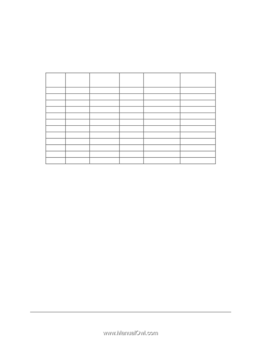
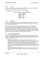
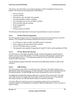
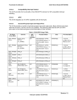
Intel® Server Board SE7505VB2 Functional Architecture 3.2.1.1 DDR Configurations The DDR interface supports up to 8 GB of main memory and supports single- and doubledensity DIMMs. The DDR can be any industry-standard DDR. The following table shows the DDR DIMM technology supported. Table 4. Supported DDRs DIMM Capacity DIMM Organization SDRAM Density SDRAM Organization # SDRAM Rows / Devices Banks / # Address Bits Rows / Banks / Column 128MB 16M x 72 128Mbit 16M x 8 9/1/4 12/2/10 256MB 32M x 72 64Mbit 16M x 4 36/2/4 12/2/10 256MB 32M x 72 128Mbit 32M x 4 18/1/4 12/2/11 256MB 32M x 72 128Mbit 16M x 8 18/2/4 12/2/10 256MB 32M x 72 256Mbit 32M x 8 9/1/4 13/2/10 512MB 64M x 72 256Mbit 64M x 4 18/1/4 13/2/11 512MB 64M x 72 256Mbit 32M x 8 18/2/4 13/2/10 512MB 64M x 72 512Mbit 64M x 8 9/1/4 13/2/11 1GB 128M x 72 256Mbit 64M x 4 36/2/4 13/2/11 1GB 128M x 72 512Mbit 64M x 8 18/2/4 13/2/11 1GB 128M x 72 512Mbit 128M x 4 18/1/4 13/2/12 2GB 256M x 72 512Mbit 128M x 4 36/2/4 13/2/12 3.2.2 Memory Controller Hub (MCH) The MCH is a 1005-ball FC-BGA device and uses the proven components of previous generations like the Intel Xeon processor bus interface unit, the hub interface unit, and the DDR memory interface unit. In addition, the MCH incorporates a hub interface (HI) . The HI interface allows the MCH to directly interface with the P64H2. The MCH also increases the main memory interface bandwidth and maximum memory configuration with a 144-bit wide memory interface. The MCH integrates the following main functions: An integrated high performance main memory subsystem. An HI 2.0 bus which provides an interface to the P64H2 An HI 1.5 bus which provides an interface to the ICH4 AGP pro slot: Video controller with 3D/2D graphics accelerator Other features provided by the MCH include the following: Full support of ECC on the processor bus Full support of Intel x4 SDDC on the memory interface with x4 DIMMs Twelve deep in-order queue, two deep defer queue Full support of registered DDR266 ECC DIMMs. Support for 2 GB DDR memory modules Memory scrubbing Revision 1.2 23 Intel part number C32194-002
-
 1
1 -
2
-
3
-
4
-
5
-
6
-
7
-
8
-
9
-
10
-
11
-
12
-
13
-
14
-
15
-
16
-
17
-
 18
18 -
 19
19 -
 20
20 -
 21
21 -
 22
22 -
 23
23 -
 24
24 -
 25
25 -
 26
26 -
 27
27 -
 28
28 -
29
-
30
-
31
-
32
-
33
-
34
-
35
-
36
-
37
-
38
-
39
-
40
-
41
-
42
-
43
-
44
-
45
-
46
-
47
-
48
-
49
-
50
-
51
-
52
-
53
-
54
-
55
-
56
-
57
-
58
-
59
-
60
-
61
-
62
-
63
-
64
-
65
-
66
-
67
-
68
-
69
-
70
-
71
-
72
-
73
-
74
-
75
-
76
-
77
-
78
-
79
-
80
-
81
-
82
-
83
-
84
-
85
-
86
-
87
-
88
-
89
-
90
-
91
-
92
-
93
-
94
-
95
-
96
-
97
-
98
-
99
-
100
-
101
-
102
-
103
-
104
-
105
-
106
-
107
-
108
 |
 |