Intel SE7505VB2 Product Specification - Page 29
GPIOs, Serial Ports, Serial - schematic
 |
View all Intel SE7505VB2 manuals
Add to My Manuals
Save this manual to your list of manuals |
Page 29 highlights
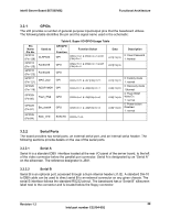
Intel® Server Board SE7505VB2 Functional Architecture 3.3.1 GPIOs The sIO provides a number of general-purpose input/output pins that the baseboard utilizes. The following table identifies the pin and the signal name used in the schematic: Table 6. Super I/O GPIO Usage Table Pin Name Pin No. GPIO12 (Pin 126) GPIO13 (Pin 125) GPIO15 (Pin 123) GPIO17 (Pin 121) GPIO20 (Pin 119) Used as CLRPAS# FanSlct1# FanSlct2# MAG_jmpr RECRYMD# GPI/GPO / Function Function Select GPI CR2A=1 & CR2A=1 & LD7 [F0h]=1 GPO CR2A=1 & CR2A=1 & LD7 [F0h]=0 GPO GPI CR2A=1 & LD7 [F0h]=1 GPI CR2A=1 & LD8[F0h]=1 GPIO25 Flash_EN# (Pin 88) GPO CR2B=1 & LD8[F0h]=0 GPIO26 (Pin 87) GPIO35 (Pin 64) Btn_dsabl# Blink_LED GPO CR2B=1 & LD8[F0h]=0 SUSLED CR29h=0 Data Description 0: Clear Password LD7[F1h] 1: Normal LD7[F1h] LD7[F1h] LD8[F1h] LD8[F1h] LD8[F1h] 0: Factory mode 1: normal 0: Recovery mode 1:Normal 0: Flash ROM Write En 1: normal 0: Power button Disabled 1: normal 3.3.2 Serial Ports The board provides two serial ports, an external serial port, and an internal serial header. The following sections provide details on the use of the serial ports. 3.3.2.1 Serial A Serial A is a standard DB9 interface located at the rear I/O panel of the server board, to the left of the video connector below the parallel port connector. Serial A is designated by as "Serial A" on the silkscreen. The reference designator is J8A1. 3.3.2.2 Serial B Serial B is an optional port, accessed through a 9-pin internal header (J1J2). A standard DH-10 to DB9 cable can be used to direct serial B to an external connector on any given chassis. The serial B interface follows the standard RS232 pinout. The baseboard has a "Serial B" silkscreen label next to the connector and is located below the floppy connector. Revision 1.2 29 Intel part number C32194-002
-
 1
1 -
2
-
3
-
4
-
5
-
6
-
7
-
8
-
9
-
10
-
11
-
12
-
13
-
14
-
15
-
16
-
17
-
18
-
19
-
20
-
21
-
22
-
23
-
 24
24 -
 25
25 -
 26
26 -
 27
27 -
 28
28 -
 29
29 -
 30
30 -
 31
31 -
 32
32 -
 33
33 -
 34
34 -
35
-
36
-
37
-
38
-
39
-
40
-
41
-
42
-
43
-
44
-
45
-
46
-
47
-
48
-
49
-
50
-
51
-
52
-
53
-
54
-
55
-
56
-
57
-
58
-
59
-
60
-
61
-
62
-
63
-
64
-
65
-
66
-
67
-
68
-
69
-
70
-
71
-
72
-
73
-
74
-
75
-
76
-
77
-
78
-
79
-
80
-
81
-
82
-
83
-
84
-
85
-
86
-
87
-
88
-
89
-
90
-
91
-
92
-
93
-
94
-
95
-
96
-
97
-
98
-
99
-
100
-
101
-
102
-
103
-
104
-
105
-
106
-
107
-
108
 |
 |
