Intel SE7505VB2 Product Specification - Page 41
Legacy Interrupt Sources, Serialized IRQ Support, IRQ Scan for PCIIRQ, PCI Error Handling
 |
View all Intel SE7505VB2 manuals
Add to My Manuals
Save this manual to your list of manuals |
Page 41 highlights
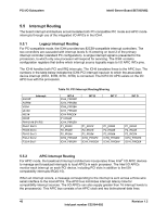
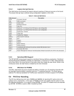
Intel® Server Board SE7505VB2 PCI I/O Subsystem 5.5.2.1 Legacy Interrupt Sources The table below recommends the logical interrupt mapping of interrupt sources on the board. The actual interrupt map is defined using configuration registers in the ICH4. Table 17. Interrupt Definitions ISA Interrupt INTR NMI IRQ0 IRQ1 IRQ2 IRQ3 IRQ4 IRQ5 IRQ6 IRQ7 IRQ8_L IRQ9 IRQ10 IRQ11 IRQ12 IRQ13 IRQ14 IRQ15 SMI* Processor interrupt. Description NMI to processor. System timer Keyboard interrupt. Slave PIC Serial port 1 or 2 interrupt from SIO device, user-configurable. Serial port 1 or 2 interrupt from SIO device, user-configurable. Parallel Port / Generic Floppy disk. Parallel Port / Generic Active low RTC interrupt. SCI* Generic Generic Mouse interrupt. Floaty processor. Compatibility IDE interrupt from primary channel IDE devices 0 and 1. Secondary IDE Cable System Management Interrupt. General purpose indicator sourced by the ICH4 to the processors. 5.5.3 Serialized IRQ Support The SE7505VB2 server board supports a serialized interrupt delivery mechanism. Serialized Interrupt Requests (SERIRQ) consists of a start frame, a minimum of 17 IRQ / data channels, and a stop frame. Any slave device in the quiet mode may initiate the start frame. While in the continuous mode, the start frame is initiated by the host controller. 5.5.4 IRQ Scan for PCIIRQ The IRQ / data frame structure includes the ability to handle up to 32 sampling channels with the standard implementation using the minimum 17 sampling channels. The board has an external PCI interrupt serializer for PCIIRQ scan mechanism of ICH4 to support 16 PCIIRQs. 5.6 PCI Error Handling The PCI bus defines two error pins, PERR# and SERR#, for reporting PCI parity errors and system errors, respectively. In the case of PERR#, the PCI bus master has the option to retry the offending transaction, or to report it using SERR#. All other PCI-related errors are reported by SERR#. SERR# is routed to NMI if enabled by BIOS. Revision 1.2 41 Intel part number C32194-002
-
 1
1 -
2
-
3
-
4
-
5
-
6
-
7
-
8
-
9
-
10
-
11
-
12
-
13
-
14
-
15
-
16
-
17
-
18
-
19
-
20
-
21
-
22
-
23
-
24
-
25
-
26
-
27
-
28
-
29
-
30
-
31
-
32
-
33
-
34
-
35
-
 36
36 -
 37
37 -
 38
38 -
 39
39 -
 40
40 -
 41
41 -
 42
42 -
 43
43 -
 44
44 -
 45
45 -
 46
46 -
47
-
48
-
49
-
50
-
51
-
52
-
53
-
54
-
55
-
56
-
57
-
58
-
59
-
60
-
61
-
62
-
63
-
64
-
65
-
66
-
67
-
68
-
69
-
70
-
71
-
72
-
73
-
74
-
75
-
76
-
77
-
78
-
79
-
80
-
81
-
82
-
83
-
84
-
85
-
86
-
87
-
88
-
89
-
90
-
91
-
92
-
93
-
94
-
95
-
96
-
97
-
98
-
99
-
100
-
101
-
102
-
103
-
104
-
105
-
106
-
107
-
108
 |
 |