Intel SE7505VB2 Product Specification - Page 50
SE7505VB2 Connectors, Main Power Connector
 |
View all Intel SE7505VB2 manuals
Add to My Manuals
Save this manual to your list of manuals |
Page 50 highlights
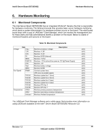
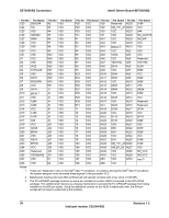
SE7505VB2 Connectors Intel® Server Board SE7505VB2 8. SE7505VB2 Connectors 8.1 Main Power Connector The main power supply connection is obtained using the 24-pin connector. The following table defines the pin-outs of the connector. Color Orange Blue Black Green Black Black Black White Red Red Red Black Table 20. Power Connector Pin-out (J9B1) Signal 3.3V -12V GND DC_ON# GND GND GND +5V +5V +5V GND Pin 13 14 15 16 17 18 19 20 21 22 23 24 Pin 1 2 3 4 5 6 7 8 9 10 11 12 Signal 3.3V 3.3V GND +5V GND +5V GND PS_GOOD SB5V +12V +12V 3.3V Color Orange Orange Black Red Black Red Black Gray Purple Yellow Yellow Orange Table 21. Auxiliary Signal Connector (J7K1) Pin 1 2 3 4 5 Signal SCL SDA PWR_Alert# GNDsens 3.3Vsens Color Green Yellow Red Black Orange Table 22. Auxiliary CPU Power Connector Pin-out (J9K1) Signal +12ENG +12ENG +12ENG +12ENG Pin 5 6 7 8 Pin 1 2 3 4 Signal GND GND GND GND 50 Revision 1.2 Intel part number C32194-002
-
 1
1 -
2
-
3
-
4
-
5
-
6
-
7
-
8
-
9
-
10
-
11
-
12
-
13
-
14
-
15
-
16
-
17
-
18
-
19
-
20
-
21
-
22
-
23
-
24
-
25
-
26
-
27
-
28
-
29
-
30
-
31
-
32
-
33
-
34
-
35
-
36
-
37
-
38
-
39
-
40
-
41
-
42
-
43
-
44
-
 45
45 -
 46
46 -
 47
47 -
 48
48 -
 49
49 -
 50
50 -
 51
51 -
 52
52 -
 53
53 -
 54
54 -
 55
55 -
56
-
57
-
58
-
59
-
60
-
61
-
62
-
63
-
64
-
65
-
66
-
67
-
68
-
69
-
70
-
71
-
72
-
73
-
74
-
75
-
76
-
77
-
78
-
79
-
80
-
81
-
82
-
83
-
84
-
85
-
86
-
87
-
88
-
89
-
90
-
91
-
92
-
93
-
94
-
95
-
96
-
97
-
98
-
99
-
100
-
101
-
102
-
103
-
104
-
105
-
106
-
107
-
108
 |
 |
