Kenmore HE2t User Guide - Page 73
Line Filter
 |
View all Kenmore HE2t manuals
Add to My Manuals
Save this manual to your list of manuals |
Page 73 highlights
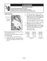
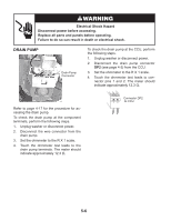
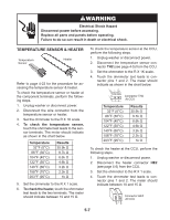
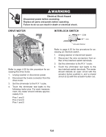
Electrical Shock Hazard Disconnect power before accessing. Replace all parts and panels before operating. Failure to do so can result in death or electrical shock. LINE FILTER Pins A & B Pins C & D Refer to page 4-8 for the procedure for accessing the line filter. To check the line filter at the component terminals, perform the following steps. 1. Unplug washer or disconnect power. 2. Disconnect the wire connectors from the line filter. 3. Set the ohmmeter to the R X 1 scale. 4. Touch the ohmmeter test leads to the fol- lowing connector pins (shown above). The meter should indicate 0 Ω for each measurement. Pins A and B Pins C and D To check the line filter at the CCU, perform the following steps. 1. Unplug washer or disconnect power. 2. Disconnect the line filter connector IF2 (see page 4-5) from the CCU. 3. Set the ohmmeter to the R X 1 scale. 4. Touch the ohmmeter test leads to connector pins 1 and 2. The meter should indicate 0 Ω. 1 2 Connector IF2 At CCU 5-3
-
 1
1 -
2
-
3
-
4
-
5
-
6
-
7
-
8
-
9
-
10
-
11
-
12
-
13
-
14
-
15
-
16
-
17
-
18
-
19
-
20
-
21
-
22
-
23
-
24
-
25
-
26
-
27
-
28
-
29
-
30
-
31
-
32
-
33
-
34
-
35
-
36
-
37
-
38
-
39
-
40
-
41
-
42
-
43
-
44
-
45
-
46
-
47
-
48
-
49
-
50
-
51
-
52
-
53
-
54
-
55
-
56
-
57
-
58
-
59
-
60
-
61
-
62
-
63
-
64
-
65
-
66
-
67
-
 68
68 -
 69
69 -
 70
70 -
 71
71 -
 72
72 -
 73
73 -
 74
74 -
 75
75 -
 76
76 -
 77
77 -
 78
78 -
79
-
80
-
81
-
82
-
83
-
84
-
85
-
86
-
87
-
88
-
89
-
90
-
91
-
92
-
93
-
94
-
95
-
96
 |
 |
