Lenovo 0768AFU User Manual - Page 51
Removing, replacing
 |
View all Lenovo 0768AFU manuals
Add to My Manuals
Save this manual to your list of manuals |
Page 51 highlights
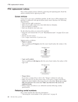
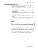
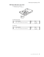
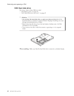
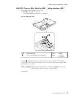
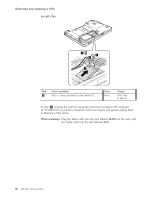
Removing and replacing a FRU Removing and replacing a FRU This section presents directions and drawings for use in removing and replacing a FRU. Be sure to observe the following general rules: 1. Do not try to service any computer unless you have been trained and certified. An untrained person runs the risk of damaging parts. 2. Before replacing any FRU, review "FRU replacement notices" on page 42. 3. Begin by removing any FRUs that have to be removed before the failing FRU. Any such FRUs are listed at the top of the page. Remove them in the order in which they are listed. 4. Follow the correct sequence in the steps for removing the FRU, as given in the drawings by the numbers in square callouts. 5. When turning a screw to replace a FRU, turn it in the direction as given by the arrow in the drawing. 6. When removing the FRU, move it in the direction as given by the arrow in the drawing. 7. To put the new FRU in place, reverse the removal procedure and follow any notes that pertain to replacement. For information about connecting and arranging internal cables, see "Locations" on page 104. 8. When replacing a FRU, use the correct screw as shown in the procedures. DANGER Before removing any FRU, turn off the computer, unplug all power cords from electrical outlets, remove the battery pack, and then disconnect any interconnecting cables. Attention: After replacing a FRU, do not turn on the computer until you have made sure that all screws, springs, and other small parts are in place and none are loose inside the computer. Verify this by shaking the computer gently and listening for rattling sounds. Metallic parts or metal flakes can cause electrical short circuits. Attention: The system board is sensitive to, and can be damaged by, electrostatic discharge. Before touching it, establish personal grounding by touching a ground point with one hand or by using an electrostatic discharge (ESD) strap (P/N 6405959). Lenovo 3000 N100 and N200 45
-
 1
1 -
2
-
3
-
4
-
5
-
6
-
7
-
8
-
9
-
10
-
11
-
12
-
13
-
14
-
15
-
16
-
17
-
18
-
19
-
20
-
21
-
22
-
23
-
24
-
25
-
26
-
27
-
28
-
29
-
30
-
31
-
32
-
33
-
34
-
35
-
36
-
37
-
38
-
39
-
40
-
41
-
42
-
43
-
44
-
45
-
 46
46 -
 47
47 -
 48
48 -
 49
49 -
 50
50 -
 51
51 -
 52
52 -
 53
53 -
 54
54 -
 55
55 -
 56
56 -
57
-
58
-
59
-
60
-
61
-
62
-
63
-
64
-
65
-
66
-
67
-
68
-
69
-
70
-
71
-
72
-
73
-
74
-
75
-
76
-
77
-
78
-
79
-
80
-
81
-
82
-
83
-
84
-
85
-
86
-
87
-
88
-
89
-
90
-
91
-
92
-
93
-
94
-
95
-
96
-
97
-
98
-
99
-
100
-
101
-
102
-
103
-
104
-
105
-
106
-
107
-
108
-
109
-
110
-
111
-
112
-
113
-
114
-
115
-
116
-
117
-
118
-
119
-
120
-
121
-
122
-
123
-
124
-
125
-
126
-
127
-
128
-
129
-
130
-
131
-
132
-
133
-
134
-
135
-
136
-
137
-
138
-
139
-
140
-
141
-
142
-
143
-
144
-
145
-
146
-
147
-
148
-
149
-
150
-
151
-
152
-
153
-
154
-
155
-
156
-
157
-
158
-
159
-
160
-
161
-
162
-
163
-
164
-
165
 |
 |