Lenovo 0768AFU User Manual - Page 92
System, board, bottom, cover, assembly, cover
 |
View all Lenovo 0768AFU manuals
Add to My Manuals
Save this manual to your list of manuals |
Page 92 highlights
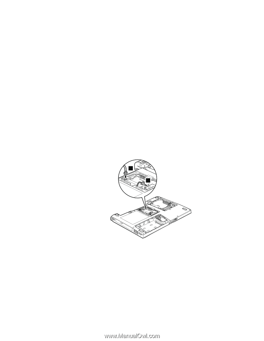
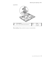
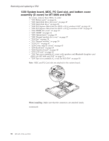
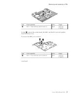
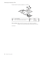
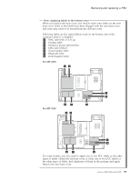
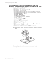
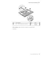
Removing and replacing a FRU 1220 System board, MDC, PC Card slot, and bottom cover assembly (D cover) for MT 0689 and 0768 For access, remove these FRUs, in order: v "1010 Battery pack" on page 46 v "1020 Hard disk drive slot cover" on page 47 v "1030 Hard disk drive" on page 48 v "1040 PCI Express Mini Card for 802.11 a/b/g wireless LAN" on page 49 v "1050 PCI Express Mini Card for 802.11 a/b/g/n wireless LAN" on page 51 v "1060 DIMM slot cover" on page 53 v "1070 DIMM" on page 54 v "1080 Optical drive" on page 55 v "1090 Thermal module slot cover" on page 57 v "1100 Fan" on page 58 v "1110 Thermal module" on page 59 v "1120 CPU" on page 62 v "1130 Cover, strip (E cover)" on page 63 v "1150 Keyboard" on page 65 v "1160 Function board" on page 68 v "1170 LCD unit" on page 69 v "1180 Top cover assembly (C cover) with speakers and Bluetooth daughter card (BDC) for MT 0689 and 0768" on page 75 v "1190 Top cover assembly (C cover) for MT 0769" on page 80 Note: MDC and PC Card slot are attached to the system board. 1 2 When installing: Make sure that the connectors are attached firmly. (continued) 86 MT 0689, 0768, and 0769
-
 1
1 -
2
-
3
-
4
-
5
-
6
-
7
-
8
-
9
-
10
-
11
-
12
-
13
-
14
-
15
-
16
-
17
-
18
-
19
-
20
-
21
-
22
-
23
-
24
-
25
-
26
-
27
-
28
-
29
-
30
-
31
-
32
-
33
-
34
-
35
-
36
-
37
-
38
-
39
-
40
-
41
-
42
-
43
-
44
-
45
-
46
-
47
-
48
-
49
-
50
-
51
-
52
-
53
-
54
-
55
-
56
-
57
-
58
-
59
-
60
-
61
-
62
-
63
-
64
-
65
-
66
-
67
-
68
-
69
-
70
-
71
-
72
-
73
-
74
-
75
-
76
-
77
-
78
-
79
-
80
-
81
-
82
-
83
-
84
-
85
-
86
-
 87
87 -
 88
88 -
 89
89 -
 90
90 -
 91
91 -
 92
92 -
 93
93 -
 94
94 -
 95
95 -
 96
96 -
 97
97 -
98
-
99
-
100
-
101
-
102
-
103
-
104
-
105
-
106
-
107
-
108
-
109
-
110
-
111
-
112
-
113
-
114
-
115
-
116
-
117
-
118
-
119
-
120
-
121
-
122
-
123
-
124
-
125
-
126
-
127
-
128
-
129
-
130
-
131
-
132
-
133
-
134
-
135
-
136
-
137
-
138
-
139
-
140
-
141
-
142
-
143
-
144
-
145
-
146
-
147
-
148
-
149
-
150
-
151
-
152
-
153
-
154
-
155
-
156
-
157
-
158
-
159
-
160
-
161
-
162
-
163
-
164
-
165
 |
 |