Panasonic AG-HVX200PJ Operating Instructions - Page 80
Video deck (Dubbing), TV/Monitor (playback/dubbing), TV/Monitor
 |
View all Panasonic AG-HVX200PJ manuals
Add to My Manuals
Save this manual to your list of manuals |
Page 80 highlights
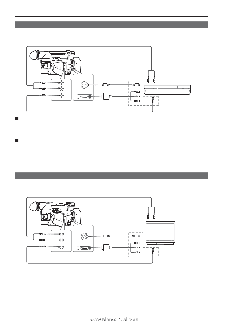
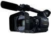
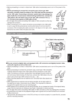
Connecting external units (continued) Video deck (Dubbing) When a component video cable is used for the connection, only the output signals from the unit will be available. Audio cable (optional) White: CH1 (left channel) sound Red: CH2 (right channel) sound CH1 IN/ AUDIO OUT CH2 IN/ OUT VIDEO Video cable (optional) S-VIDEO IN/OUT S-video cable (optional) COMPONENT OUT Component video cable (included) VCR Connect one of these cables to the terminal on the video deck. Connect to the output terminal on the external device when the video signals and audio signals of an external device are to be input to the unit. (Tape mode only) Connect to the input terminal on the external device when the unit's video signals and audio signals are to be output to an external device. • Except when performing audio dubbing on existing recordings, audio signals cannot be recorded unless video signals are input to the S-VIDEO IN/OUT connector and/or VIDEO IN/OUT jack. • The signals of the S-VIDEO IN/OUT terminal take priority over the signals of the VIDEO IN/ OUT terminal. TV/Monitor (playback/dubbing) When a component video cable is used for the connection, only the output signals from the unit will be available. Audio cable (optional) White: CH1 (left channel) sound Red: CH2 (right channel) sound CH1 IN/ AUDIO OUT CH2 IN/ OUT VIDEO Video cable (optional) S-VIDEO IN/OUT S-video cable (optional) COMPONENT OUT Component video cable (included) TV/Monitor Connect one of these cables to the terminal on the television. • When the COMPONENT OUT connectors and the S-VIDEO OUT or VIDEO OUT connector have been connected concurrently, the COMPONENT OUT connectors take priority. Signals cannot be output through both sets of connectors at the same time. • When connecting the camera to another device using the component video cable, if the terminal on the device to which it is to be connected is a BNC type, use the pin-BNC conversion plug provided. 80
-
 1
1 -
2
-
3
-
4
-
5
-
6
-
7
-
8
-
9
-
10
-
11
-
12
-
13
-
14
-
15
-
16
-
17
-
18
-
19
-
20
-
21
-
22
-
23
-
24
-
25
-
26
-
27
-
28
-
29
-
30
-
31
-
32
-
33
-
34
-
35
-
36
-
37
-
38
-
39
-
40
-
41
-
42
-
43
-
44
-
45
-
46
-
47
-
48
-
49
-
50
-
51
-
52
-
53
-
54
-
55
-
56
-
57
-
58
-
59
-
60
-
61
-
62
-
63
-
64
-
65
-
66
-
67
-
68
-
69
-
70
-
71
-
72
-
73
-
74
-
 75
75 -
 76
76 -
 77
77 -
 78
78 -
 79
79 -
 80
80 -
 81
81 -
 82
82 -
 83
83 -
 84
84 -
 85
85 -
86
-
87
-
88
-
89
-
90
-
91
-
92
-
93
-
94
-
95
-
96
-
97
-
98
-
99
-
100
-
101
-
102
-
103
-
104
-
105
-
106
-
107
-
108
-
109
-
110
-
111
-
112
-
113
-
114
-
115
-
116
-
117
-
118
-
119
-
120
-
121
-
122
-
123
-
124
-
125
-
126
-
127
-
128
-
129
-
130
-
131
-
132
-
133
-
134
-
135
-
136
-
137
-
138
 |
 |