Panasonic AW-RP150GJ AW-RP150 Operation Manual - Operating Instructions - Page 10
Menu operation ENABLE button [ENABLE], PAN/TILT SPEED dial [SPEED]
 |
View all Panasonic AW-RP150GJ manuals
Add to My Manuals
Save this manual to your list of manuals |
Page 10 highlights
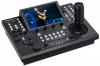
Parts and their functions (continued) Menu operation ENABLE button [ENABLE] Enables or disables operations with the menu operation section, user button section, and LCD panel. Hold down to turn the LCD panel off. Button indicator on : Operations with the menu operation section, user button section, and LCD panel are enabled. Button indicator off : Operations with the menu operation section, user button section, and LCD panel are disabled. Cursor movement buttons Moves the cursor on the menu screen up or down one line. When the PICTURE button is on, use this to switch the crop frame. Camera selection section 1 2 3 4 5 6 7 8 9 10 CAMERA / GROUP SELECTION 1 2 3 4 5 11 12 13 14 15 6 7 8 9 10 11-20 16 17 18 19 20 SELECT CAMERA GROUP Mode selection button [SELECT] Each press of this switches the operation mode of the camera selection buttons (), changing as follows; Off → On (with camera group 1 to 10 selected) → On (with camera group 11 to 20 selected) and the [11-20] indicator (camera group 11 to 20). Button indicator off : Camera selection mode Button indicator on : Camera group selection mode (1 to 10). Camera group selection mode (11 to 20). (The [11-20] indicator lights at this time.) Pan and tilt section ENABLE PAN LOW HI SPEED TILT PAN/TILT lever Use this to control the direction in which the currently selected remote camera points. The movement speed differs depending on the angle to which the PAN/TILT lever is moved. Moved left or right : The camera points to the left or right. Moved toward you or away from you: The camera points up or down. zzWhen the [PAN DIR] and [TILT DIR] items in the [PTZ INFO2] FUNCTION menu are set to "REVERSE", it is possible to change the relationship between the direction that the lever is tilted and the direction the camera moves. Note zzWhen turning on the power, do not touch until the status screen is displayed on the LCD panel. ZOOM/FOCUS rocker You can control the focus or zoom function by allocating this button. Note zzWhen turning on the power, do not touch until the status screen is displayed on the LCD panel. Camera selection buttons [CAMERA / GROUP SELECTION 1 to 10] Use these to select the remote camera or camera group to control from the unit. Pressing any of [1] to [10] in camera selection mode switches to the corresponding remote camera. Pressing any of [1] to [10] in camera group selection mode switches to the corresponding camera group and turns on the corresponding camera group indicator (). After a camera group is selected, the camera selection buttons return to the camera selection mode. zzWhen in the camera group selection mode, the camera selection buttons light blue. Only the button for the camera group currently selected lights amber. Camera group indicators [CAMERA GROUP 1 to 20] The indicator for the selected camera group number is on. When a camera group between 11 and 20 is selected, the [11-20] indicator lights. Camera status indicators [1] to [10] These indicate the statuses of the remote cameras assigned to [1] to [10]. For details, refer to "Selecting a remote camera" (page 24). PAN/TILT SPEED dial [SPEED] Use this to adjust the operation speed variation amount for PAN/TILT lever operation. Turned clockwise : Operation is at a higher speed (HI) Turned counterclockwise : Operation is at a lower speed (LOW) PAN/TILT ENABLE button [ENABLE] Use this to enable the PAN/TILT lever and ZOOM/FOCUS rocker. Button indicator on : PAN/TILT lever operation is enabled. (Amber) Button indicator off : PAN/TILT lever operation is disabled. (Hold down the button) zzWhen the PICTURE button is on, this button turns green when you press it and it switches to operate the crop frame. 10
-
 1
1 -
2
-
3
-
4
-
 5
5 -
 6
6 -
 7
7 -
 8
8 -
 9
9 -
 10
10 -
 11
11 -
 12
12 -
 13
13 -
 14
14 -
 15
15 -
16
-
17
-
18
-
19
-
20
-
21
-
22
-
23
-
24
-
25
-
26
-
27
-
28
-
29
-
30
-
31
-
32
-
33
-
34
-
35
-
36
-
37
-
38
-
39
-
40
-
41
-
42
-
43
-
44
-
45
-
46
-
47
-
48
-
49
-
50
-
51
-
52
-
53
-
54
-
55
-
56
-
57
-
58
-
59
-
60
-
61
-
62
-
63
-
64
-
65
-
66
-
67
-
68
-
69
-
70
-
71
-
72
-
73
-
74
-
75
-
76
-
77
-
78
-
79
-
80
-
81
-
82
-
83
-
84
-
85
-
86
-
87
-
88
-
89
-
90
-
91
-
92
-
93
-
94
-
95
-
96
-
97
-
98
 |
 |
