Panasonic AW-RP150GJ AW-RP150 Operation Manual - Operating Instructions - Page 15
Precautions for installation, Example of embedding the unit in a desktop
 |
View all Panasonic AW-RP150GJ manuals
Add to My Manuals
Save this manual to your list of manuals |
Page 15 highlights
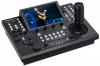
Precautions for installation In addition to the safety precautions given in "Read this first!", also observe the following instructions. Be sure to ask your dealer to perform the installation and connection work for the unit. Connecting a power supply zzInsert the DC plug for the external DC power supply all the way in until it locks into place. 3G SDI IN POWER ON 5 SERIAL CONT 4 3 2 1 IP CONT LINK ACT 12V IN LAN RS-442 DC plug Do not allow any foreign objects to enter inside the unit zzAllowing water, metal items, food or drink, or other foreign objects to enter inside the unit may cause a fire or electric shock. Installation location zzThis unit is designed for indoor use only. zzInstall and use the unit in a stable location. zzAvoid installing the unit where it will be exposed to direct sunlight. zzInstalling the unit in a location with a lot of humidity, dust, or vibration may result in a failure. zzWhen the unit will not be used for a long time, turn off the power switch and remove the DC plug for the external DC power supply to save power. Example of embedding the unit in a desktop When you will use the unit embedded in a desktop, refer to the following procedure. 1. Make mount angles suitable for the installation location. zzDesk mounting side Unit: mm (inch) 3. Insert the unit into the desktop hole and then fix it in place with four screws. 25 (31/32) 160 (6-5/16) Ø5 (3/16) (Desk mounting holes) zzUnit mounting side 210 (8-9/32) 140 (5-1/2) Ø3.5 (1/8) (Unit mounting hole) 2 (3/32) 21 (13/16) 35 (1-3/8) 30 (1-3/16) 2. Attach the mount angles to the sides of the unit with four M3 screws. Unit zzProvide screws that match the size of the desktop mounting holes (e.g. Ø5 mm [3/16 inches]). 4. If necessary, make and attach a panel to cover the rest of desktop hole. Panel to cover hole M3 screws Mount angle Note zzFor details on the dimensions for attaching mount angles to the unit, refer to "Appearance" (page 91). 15
-
 1
1 -
2
-
3
-
4
-
5
-
6
-
7
-
8
-
9
-
 10
10 -
 11
11 -
 12
12 -
 13
13 -
 14
14 -
 15
15 -
 16
16 -
 17
17 -
 18
18 -
 19
19 -
 20
20 -
21
-
22
-
23
-
24
-
25
-
26
-
27
-
28
-
29
-
30
-
31
-
32
-
33
-
34
-
35
-
36
-
37
-
38
-
39
-
40
-
41
-
42
-
43
-
44
-
45
-
46
-
47
-
48
-
49
-
50
-
51
-
52
-
53
-
54
-
55
-
56
-
57
-
58
-
59
-
60
-
61
-
62
-
63
-
64
-
65
-
66
-
67
-
68
-
69
-
70
-
71
-
72
-
73
-
74
-
75
-
76
-
77
-
78
-
79
-
80
-
81
-
82
-
83
-
84
-
85
-
86
-
87
-
88
-
89
-
90
-
91
-
92
-
93
-
94
-
95
-
96
-
97
-
98
 |
 |
