Philips DVDR75 User manual - Page 15
Connecting to a TV and a two-channel Stereo, Stereo has Dolby Pro Logic or right/left Audio In jacks
 |
View all Philips DVDR75 manuals
Add to My Manuals
Save this manual to your list of manuals |
Page 15 highlights
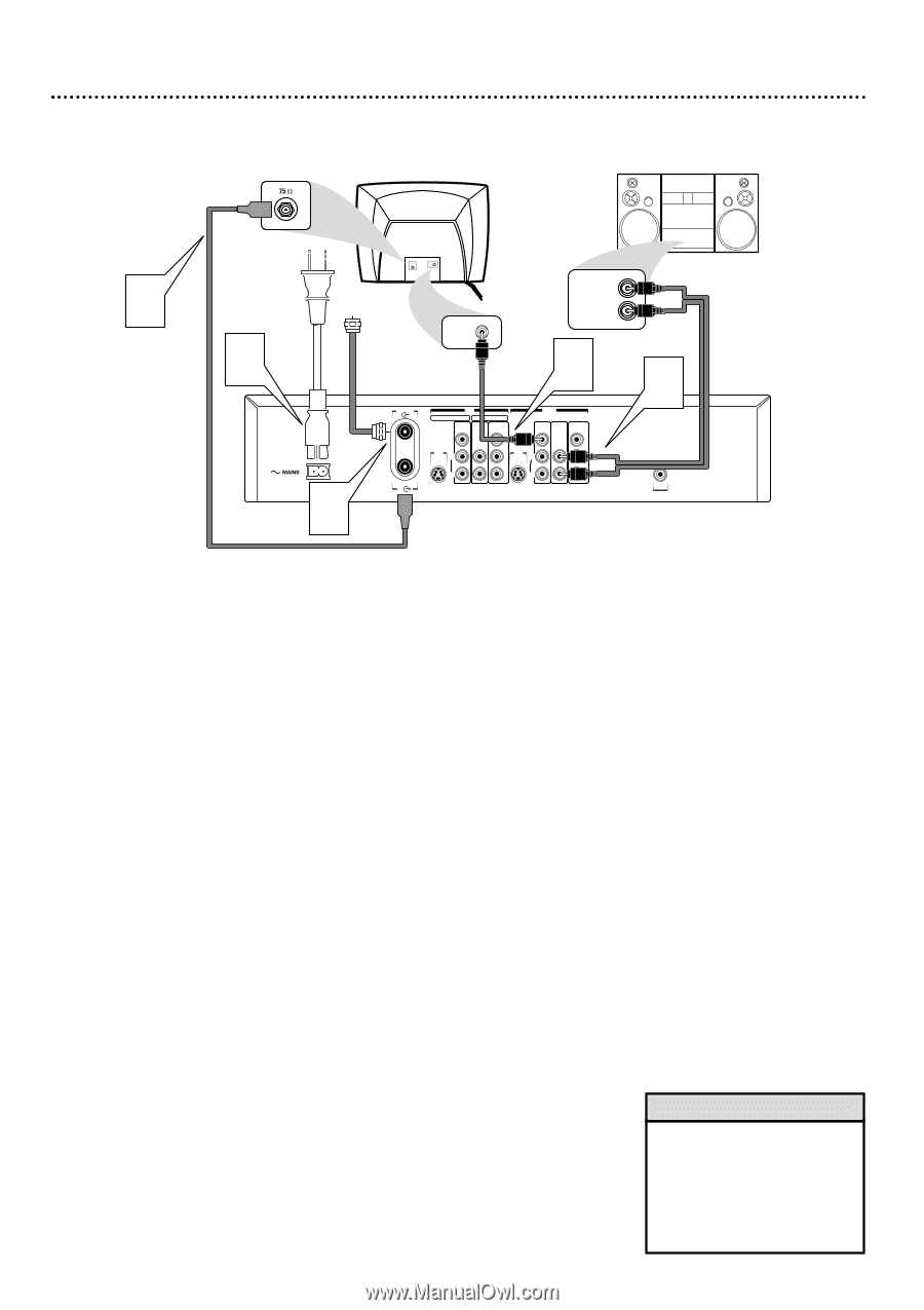
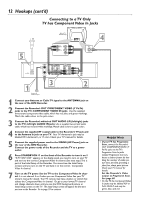
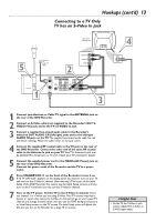
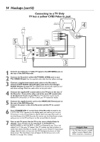
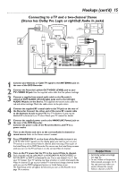
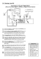
Hookups (cont'd) 15 Connecting to a TV and a two-channel Stereo (Stereo has Dolby Pro Logic or right/left Audio In jacks) Stereo (example only) 4 5 Antenna or Cable TV Signal VIDEO IN Back of TV (example only) RIGHT AUDIO IN VIDEO IN LEFT AUDIO IN 2 1 ANTENNA TV IN EXT 2 EXT 1 VIDEO AUDIO COMPONENT (CVBS) VIDEO OUT VIDEO AUDIO COMPONENT (CVBS) VIDEO Y Y S-VIDEO S-VIDEO (Y/C) L PB (Y/C) L PB AUDIO AUDIO R PR R PR 3 DIGITAL AUDIO OUT 1 Connect your Antenna or Cable TV signal to the ANTENNA jack on the rear of the DVD Recorder. 2 Connect the Recorder's yellow OUT VIDEO (CVBS) jack to your TV's VIDEO IN jack. Use the supplied video cable that has yellow markings. 3 Connect a supplied two-strand audio cable to the Recorder's white/red OUT AUDIO L/R (left/right) jacks and to the left/right AUDIO IN jacks on the Stereo. The supplied two-strand audio cable has red and white markings. Match the cable colors to the jack colors. 4 Connect the supplied RF coaxial cable to the TV jack on the rear of the Recorder. Connect the other end of the same RF coaxial cable to the Antenna In jack on your TV. Your TV's Antenna In jack may be labelled RF In,Antenna In, or 75 ohm. Check your TV manual for details. 5 Connect the supplied power cord to the MAINS (AC Power) jack on the rear of the DVD Recorder. Connect the power cords of the Recorder, Stereo, and TV to a power outlet. 6 Turn on the Stereo and set it to the correct Audio In channel or sound source. Refer to the Stereo owner's manual. 7 Press STANDBY-ON y on the front of the Recorder to turn it on. If "IS TV ON? CO3" appears on the display panel, you need to turn on your TV and set it to the correct Video In channel. (See next step.) This is part of the Initial Setup of the DVD Recorder.You cannot see the Initial Setup screens until you turn on the TV and have it on the correct Video In channel. 8 Turn on the TV power. Set the TV to the correct Video In channel. Such channels may be called AUX or AUXILIARY IN,AUDIO/VIDEO or A/V IN, EXT1 or EXT2 or External In, etc. This is not channel 3 or 4. See your TV manual. Your TV remote may have a button or switch that selects the Video In channel. Or, go to your lowest TV channel and change channels down until you see the DVD background picture or Initial Setup screen. The Initial Setup screen will appear the first time you turn on the Recorder. Go to page 18 to continue. Helpful Hints • Set Analog output accordingly. See page 62. • To use S-Video or Component Video instead, see pages 12-13. You only need one video connection. Choose the correct Video In channel at the TV.
-
 1
1 -
2
-
3
-
4
-
5
-
6
-
7
-
8
-
9
-
 10
10 -
 11
11 -
 12
12 -
 13
13 -
 14
14 -
 15
15 -
 16
16 -
 17
17 -
 18
18 -
 19
19 -
 20
20 -
21
-
22
-
23
-
24
-
25
-
26
-
27
-
28
-
29
-
30
-
31
-
32
-
33
-
34
-
35
-
36
-
37
-
38
-
39
-
40
-
41
-
42
-
43
-
44
-
45
-
46
-
47
-
48
-
49
-
50
-
51
-
52
-
53
-
54
-
55
-
56
-
57
-
58
-
59
-
60
-
61
-
62
-
63
-
64
-
65
-
66
-
67
-
68
-
69
-
70
-
71
-
72
 |
 |