Philips DVDR75 User manual - Page 25
Rear Panel
 |
View all Philips DVDR75 manuals
Add to My Manuals
Save this manual to your list of manuals |
Page 25 highlights
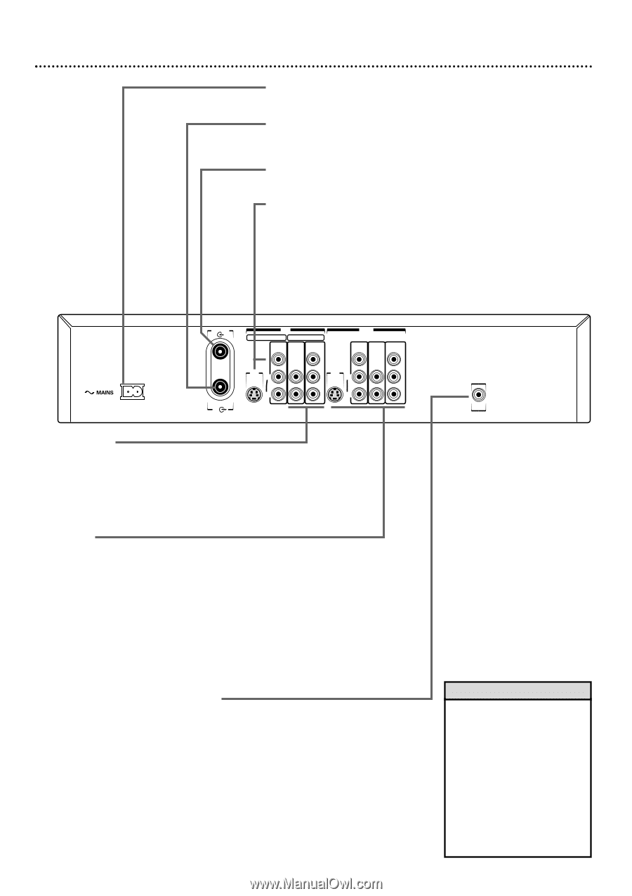
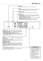
Rear Panel 25 MAINS jack Connect the supplied AC power cord here. See pages 10-16. TV jack Connect the supplied RF coaxial cable to the Recorder's TV jack and to the RF IN or ANTENNA IN jack (75 ohm) on your television. ANTENNA jack Connect your antenna or Cable TV signal here. See pages 10-16. IN EXT 2 jacks Use these jacks to receive picture and sound from other equipment. • VIDEO (CVBS): Use a video cable to connect this jack to the Video Out jack of other equipment. See page 17. • AUDIO L/R (left/right): Connect audio cables here and to the AUDIO OUT jacks of other equipment. See page 17. • S-VIDEO (Y-C): Use an S-video cable to connect this jack to the S- Video Out jack of optional additional equipment. See page 17. ANTENNA TV IN EXT 2 EXT 1 VIDEO AUDIO COMPONENT (CVBS) VIDEO OUT VIDEO AUDIO COMPONENT (CVBS) VIDEO Y Y S-VIDEO S-VIDEO (Y/C) L PB (Y/C) L PB AUDIO AUDIO R PR R PR IN EXT 1 jacks Use these jacks to receive picture and sound from other equipment. • AUDIO L/R (left/right): Connect audio cables here and to the AUDIO OUT jacks of other equipment. See page 17. • COMPONENT VIDEO (Y PB PR): Connect these jacks to the Component Video Out jacks of optional video equipment (for example, a DVD Player). See page 17. OUT jacks Use these jacks to connect the DVD Recorder directly to your TV and/or Stereo. VIDEO (CVBS): Connect the supplied video cable (yellow) here and to the TV's Video In jack. See page 14. S-VIDEO (Y-C): Connect an S-Video cable here and to a TV's SVideo In jack. See page 13. COMPONENT VIDEO (Y PB PR): Connect the supplied three-strand component video cable here and to the Component Video In jacks of a TV. See page 12. AUDIO L/R (Left/Right): Use the supplied audio cables (red and white) to connect these jacks to the Audio In jacks of a TV or Stereo. See pages 12-15. Coaxial DIGITAL AUDIO OUT jack Connect a digital audio coaxial cable here and to the digital audio coaxial In jack of a Stereo. See page 16. DIGITAL AUDIO OUT Helpful Hints • Use the same EXT (external) number for each pair of audio and video connections. For example, if you use IN EXT 2 S-VIDEO (Y/C), use the IN EXT 2 AUDIO L/R jacks. • Do not touch the inner pins of the jacks. Electrostatic discharge may damage the unit permanently. • You only need one audio and one video connection to a TV. You might not use all the jacks.
-
 1
1 -
2
-
3
-
4
-
5
-
6
-
7
-
8
-
9
-
10
-
11
-
12
-
13
-
14
-
15
-
16
-
17
-
18
-
19
-
 20
20 -
 21
21 -
 22
22 -
 23
23 -
 24
24 -
 25
25 -
 26
26 -
 27
27 -
 28
28 -
 29
29 -
 30
30 -
31
-
32
-
33
-
34
-
35
-
36
-
37
-
38
-
39
-
40
-
41
-
42
-
43
-
44
-
45
-
46
-
47
-
48
-
49
-
50
-
51
-
52
-
53
-
54
-
55
-
56
-
57
-
58
-
59
-
60
-
61
-
62
-
63
-
64
-
65
-
66
-
67
-
68
-
69
-
70
-
71
-
72
 |
 |