Philips MX6000I User manual - Page 11
Connections - ethernet
 |
View all Philips MX6000I manuals
Add to My Manuals
Save this manual to your list of manuals |
Page 11 highlights
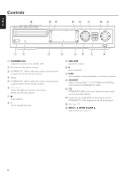
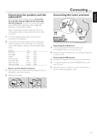
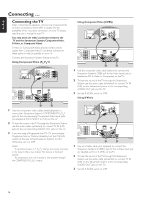
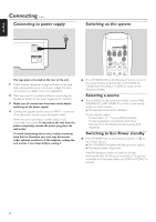
English Connections %$ # @ FRONT LEFT FRONT RIGHT CENTRE SURR LEFT SURR RIGHT ETHERNET SUB-W LEFT SUB-W RIGHT DIGITAL OUT DIGITAL IN CVBS L R P-SCAN AUX IN TV IN LINE OUT S - VIDEO ON OFF AUDIO VIDEO OUT COMPONENT ANTENNA AM FM 1 2 3456 7 8 9 0! 1 FRONT LEFT, FRONT RIGHT, CENTRE, SURR LEFT, SURR RIGHT FRONT LEFT: connect the front left speaker FRONT RIGHT: connect the front right speaker CENTRE: connect the center speaker SURR LEFT: connect the surround left speaker SURR RIGHT: connect the surround right speaker 2 SUB-W LEFT, SUB-W RIGHT connect the left and right subwoofers 3 AUX IN L, R connect to the left and right analog audio output jacks of external equipment (e. g. tape deck,VCR, ...) 4 TV IN L, R connect to the left and right AUDIO OUT jacks of the TV 5 LINE OUT L, R connect to the left and right analog audio input jacks of an external equipment (e. g. tape deck, ...) 6 VIDEO OUT/CVBS connect to the Composite Video input of the TV 7 VIDEO OUT/S-VIDEO connect to S-Video input of the TV 8 COMPONENT P , P ,Y RB connect to the corresponding Component video inputs of the TV 9 P-SCAN to switch on or off progressive scan 0 ANTENNA / AM connect the AM loop antenna ! ANTENNA / FM connect the FM antenna cable @ MAINS ~ After all other connections have been made, connect the power cable to the power outlet. # ETHERNET connect to router, broadband Internet, or PC $ DIGITAL OUT connect to the digital coaxial input of digital equipment % DIGITAL IN connect to the digital coaxial output of digital equipment Before starting with the connections, make sure all equipment you want to connect - as well as the Streamium System - are disconnected from the power outlets. 11
-
 1
1 -
2
-
3
-
4
-
5
-
 6
6 -
 7
7 -
 8
8 -
 9
9 -
 10
10 -
 11
11 -
 12
12 -
 13
13 -
 14
14 -
 15
15 -
 16
16 -
17
-
18
-
19
-
20
-
21
-
22
-
23
-
24
-
25
-
26
-
27
-
28
-
29
-
30
-
31
-
32
-
33
-
34
-
35
-
36
-
37
-
38
-
39
-
40
-
41
-
42
-
43
-
44
-
45
-
46
-
47
-
48
-
49
-
50
-
51
-
52
-
53
-
54
-
55
 |
 |
