Samsung SPH700AE User Manual (ENGLISH) - Page 32
Connecting to PC
 |
UPC - 036725240216
View all Samsung SPH700AE manuals
Add to My Manuals
Save this manual to your list of manuals |
Page 32 highlights
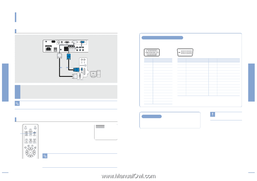
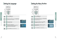
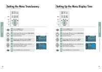
Connecting to PC Connecting to PC Connecting to PC You can connect a PC to the projector and use it as a monitor. Using PC Video Cable or DVI Cable Rear side of Projector Rear Connection DVI-D Video Cable PC Video Cable or DVI-D Port Connect PC (RGB In) port on the rear side of the projector to the monitor output port of PC using PC video cable. 1 I If PC has a DVI output port, connect it to DVI port of the projector. This product supports Plug & Play. No driver installation is needed for Windows XP. NOTE Viewing the PC Screen PC 1 1 Turn on the projector and press the PC button to select PC. If the projector is connected to PC DVI, press the DVI button to select DVI. I If PC Mode is not available, check PC video cable is in place. 2 Turn on the PC and set the PC Environment when necessary. (Page 61) 3 Adjust the screen. (Pages 64~68) I Enjoy better picture quality by using DVI-D cable (supports digital signals only) NOTE instead of PC Video cable. I DVI-I cable (supports analog signals) is not supported. Use DVD-D cable. I Sound comes out from PC speakers. 62 Pin Configuration of PC Video Port Plug PC Video Cable (15-pin signal) DVI-D (supports only digital signals) Pin No. 1 2 3 4 5 6 7 8 9 10 11 12 13 14 15 PC Input Red (R) Green (G) Blue (B) Ground Ground (DDC) Red (R) Ground Green (G) Ground Blue (B) Ground Reserved Ground Sync Ground Data (DDC) Horizontal Sync Vertical Sync Clock (DDC) Pin No. 1 2 3 4 5 6 7 8 9 10 11 12 Signal T.M.D.S. DATA2T.M.D.S. DATA2+ T.M.D.S. DATA2/4 Shield T.M.D.S. DATA4T.M.D.S. DATA4+ Clock (DDC) Data (DDC) No Connection T.M.D.S. DATA1T.M.D.S. DATA1+ T.M.D.S. DATA1/3 Shield T.M.D.S. DATA3- Pin No. 13 14 15 16 17 18 19 20 21 22 23 24 Signal T.M.D.S. DATA3+ +5V Power Ground for 5V Hot Plug Detect T.M.D.S. DATA0T.M.D.S. DATA0+ T.M.D.S. DATA0/5 Shield T.M.D.S. DATA5T.M.D.S. DATA5+ T.M.D.S. Clock Shield T.M.D.S. Clock+ T.M.D.S. Clock- VESA Plug & Play This appliance supports VESA Plug & Play and recognizes connection to PC automatically. DVI-D cable does not support CAUTION analog RGB signals. 63 Connecting to PC Connecting to PC
-
 1
1 -
2
-
3
-
4
-
5
-
6
-
7
-
8
-
9
-
10
-
11
-
12
-
13
-
14
-
15
-
16
-
17
-
18
-
19
-
20
-
21
-
22
-
23
-
24
-
25
-
26
-
 27
27 -
 28
28 -
 29
29 -
 30
30 -
 31
31 -
 32
32 -
 33
33 -
 34
34 -
 35
35 -
 36
36 -
 37
37 -
38
-
39
-
40
-
41
-
42
 |
 |