Sony DSR 45A Operating Instructions - Page 12
Location and Function of Parts, Front Panel
 |
UPC - 027242689602
View all Sony DSR 45A manuals
Add to My Manuals
Save this manual to your list of manuals |
Page 12 highlights
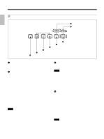
LoLcoatcioantaiondnFaunncdtioFn uofnPcatrtison of Parts Chapter 1 Overview Front Panel 1 Cassette compartment 2 REMOTE/LOCAL switch 3 ON/STANDBY switch and lamp 4 TIMER selector 5 AUDIO MONITOR selector 6 PHONE LEVEL control knob 7 PHONES jack 1 CH- CH- 1/2 3/4 MIN MAX 8 RESET button 1 Monitor display section (see page 14 (GB)) 9 CHARACTER DISPLAY (MONITOR OUT) switch 4 Display window (see page 19 (GB)) qa EJECT button CH-1 CH-2 3 Audio control section (see page 18 (GB)) CH-3 CH-4 2 Tape transport control section (see page 16 (GB)) 0 INPUT SELECT selector 1 Cassette compartment Insert a standard-size or mini-size DVCAM cassette. To open or close the compartment, press the EJECT button qa. For details of cassettes that can be used, see "Notes on Video Cassettes" on page 30 (GB). 2 REMOTE/LOCAL switch Set this switch to REMOTE when controlling the unit from an external device connected to the RS-422A/RS232C connector on the rear panel. REMOTE: Enables an external device connected to the RS-422A/RS-232C connector. When setting this switch to REMOTE, you can restrict the tape transport and menu control buttons on the front panel, the Remote Commander, and the optional Remote Control Unit connected to the CONTROL S IN jack using LOCAL ENBL on the REMOTE menu. For details on the REMOTE menu, see "REMOTE menu" on page 80 (GB). LOCAL: Disables an external device connected to the RS-422A/RS-232C connector. 12 (GB) Chapter 1 Overview The switch setting enables/disables external devices as follows. REMOTE RS-422Aa) Enabled RS-232Ca) Enabled LANCa) Enabled CONTROL S IN b) Depending on the setting of LOCAL ENBL on the REMOTE menu Remote Commander b) Depending on the setting of LOCAL ENBL on the REMOTE menu DV (i.LINK) Enabled LOCAL Disabled Disabled Enabled Enabled Enabled Enabled a) You also need to set the remote selector on the rear panel according to the connector to which you connect a device. b) Depending on the setting of COMMANDER on the OTHERS menu. Notes • An external device connected to the LANC jack can operate the unit regardless the setting of this switch as long as the remote selector is set to LANC.
-
 1
1 -
2
-
3
-
4
-
5
-
6
-
 7
7 -
 8
8 -
 9
9 -
 10
10 -
 11
11 -
 12
12 -
 13
13 -
 14
14 -
 15
15 -
 16
16 -
 17
17 -
18
-
19
-
20
-
21
-
22
-
23
-
24
-
25
-
26
-
27
-
28
-
29
-
30
-
31
-
32
-
33
-
34
-
35
-
36
-
37
-
38
-
39
-
40
-
41
-
42
-
43
-
44
-
45
-
46
-
47
-
48
-
49
-
50
-
51
-
52
-
53
-
54
-
55
-
56
-
57
-
58
-
59
-
60
-
61
-
62
-
63
-
64
-
65
-
66
-
67
-
68
-
69
-
70
-
71
-
72
-
73
-
74
-
75
-
76
-
77
-
78
-
79
-
80
-
81
-
82
-
83
-
84
-
85
-
86
-
87
-
88
-
89
-
90
-
91
-
92
-
93
-
94
-
95
-
96
-
97
-
98
-
99
-
100
-
101
-
102
-
103
-
104
-
105
-
106
-
107
-
108
-
109
-
110
-
111
-
112
-
113
-
114
-
115
-
116
-
117
-
118
-
119
-
120
-
121
-
122
-
123
-
124
-
125
-
126
-
127
-
128
-
129
-
130
-
131
-
132
-
133
-
134
-
135
-
136
-
137
-
138
-
139
-
140
-
141
-
142
-
143
-
144
-
145
-
146
-
147
-
148
-
149
-
150
-
151
-
152
-
153
-
154
-
155
-
156
-
157
-
158
-
159
-
160
-
161
-
162
-
163
-
164
-
165
-
166
-
167
-
168
-
169
-
170
-
171
-
172
-
173
-
174
-
175
-
176
-
177
-
178
-
179
-
180
-
181
-
182
-
183
-
184
-
185
-
186
-
187
-
188
-
189
-
190
-
191
-
192
-
193
-
194
-
195
-
196
-
197
-
198
-
199
-
200
-
201
-
202
-
203
-
204
-
205
-
206
-
207
-
208
-
209
-
210
-
211
-
212
-
213
-
214
-
215
-
216
-
217
-
218
-
219
-
220
 |
 |
