Sony DSR 45A Operating Instructions - Page 23
Audio signal input/output AUDIO IN jacks
 |
UPC - 027242689602
View all Sony DSR 45A manuals
Add to My Manuals
Save this manual to your list of manuals |
Page 23 highlights
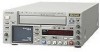
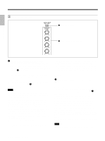
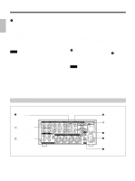
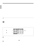
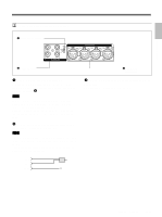
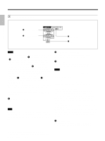
Chapter 1 Overview 2 Audio signal input/output section 1 INPUT LEVEL selector 2 AUDIO IN jacks 3 AUDIO OUT connectors 1 INPUT LEVEL (-10/-2/+4) selector Selects one from among -10 dB, -2 dB, or +4 dB according to the audio level of the signal input via the AUDIO IN jacks 2. Note If this selector setting is not appropriate, clipping distortion or noise may occur even if the AUDIO INPUT switch has been set to AUTO. For more information on the setting of this selector, see "When you set the INPUT LEVEL selector" on page 96 (GB). 2 AUDIO IN CH-1 to CH-4 jacks (phono jack) Inputs audio signals (CH-1 to CH-4). Note To input balanced audio signals via these jacks, use a conversion cable as shown below. (The COLD side is open.) For details on conversion cables, refer to the instruction manual of the devices you use. GND HOT COLD × 3 AUDIO OUT CH-1 to CH-4 connectors (XLR 3pin, male) Outputs audio signals (CH-1 to CH-4). 23 Chapter 1 Overview (GB)
-
 1
1 -
2
-
3
-
4
-
5
-
6
-
7
-
8
-
9
-
10
-
11
-
12
-
13
-
14
-
15
-
16
-
17
-
 18
18 -
 19
19 -
 20
20 -
 21
21 -
 22
22 -
 23
23 -
 24
24 -
 25
25 -
 26
26 -
 27
27 -
 28
28 -
29
-
30
-
31
-
32
-
33
-
34
-
35
-
36
-
37
-
38
-
39
-
40
-
41
-
42
-
43
-
44
-
45
-
46
-
47
-
48
-
49
-
50
-
51
-
52
-
53
-
54
-
55
-
56
-
57
-
58
-
59
-
60
-
61
-
62
-
63
-
64
-
65
-
66
-
67
-
68
-
69
-
70
-
71
-
72
-
73
-
74
-
75
-
76
-
77
-
78
-
79
-
80
-
81
-
82
-
83
-
84
-
85
-
86
-
87
-
88
-
89
-
90
-
91
-
92
-
93
-
94
-
95
-
96
-
97
-
98
-
99
-
100
-
101
-
102
-
103
-
104
-
105
-
106
-
107
-
108
-
109
-
110
-
111
-
112
-
113
-
114
-
115
-
116
-
117
-
118
-
119
-
120
-
121
-
122
-
123
-
124
-
125
-
126
-
127
-
128
-
129
-
130
-
131
-
132
-
133
-
134
-
135
-
136
-
137
-
138
-
139
-
140
-
141
-
142
-
143
-
144
-
145
-
146
-
147
-
148
-
149
-
150
-
151
-
152
-
153
-
154
-
155
-
156
-
157
-
158
-
159
-
160
-
161
-
162
-
163
-
164
-
165
-
166
-
167
-
168
-
169
-
170
-
171
-
172
-
173
-
174
-
175
-
176
-
177
-
178
-
179
-
180
-
181
-
182
-
183
-
184
-
185
-
186
-
187
-
188
-
189
-
190
-
191
-
192
-
193
-
194
-
195
-
196
-
197
-
198
-
199
-
200
-
201
-
202
-
203
-
204
-
205
-
206
-
207
-
208
-
209
-
210
-
211
-
212
-
213
-
214
-
215
-
216
-
217
-
218
-
219
-
220
 |
 |
