Toshiba A105 S4064 Maintenance Manual - Page 135
Communication (COMM), 10 Peripheral, Diagnostic Programs
 |
UPC - 032017706019
View all Toshiba A105 S4064 manuals
Add to My Manuals
Save this manual to your list of manuals |
Page 135 highlights
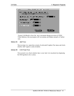
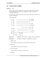
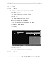
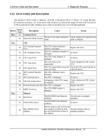
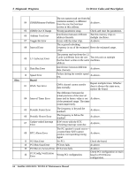
3.10 Peripheral 3 Diagnostic Programs 3.9 Communication (COMM) Subtest 01 LPT This test item is to check whether there is open or short circuit issue in the external pins by looping back the external pins, controlling the voltage of each data pin, control pin and status pin. The test requires an external connector to insert into the tested LPT port. Below is the connector's description. Fixture Description: (9) + PD7 (8) + PD6 (7) + PD5 (6) + PD4 (5) + PD3 (15) -ERROR (14) -AUTFD (13) (16) -PINIT (1) - STROBE (4) + PD2 (3) + PD1 (2) +PD0 Note: (1)~(17) -------- Pin number (10) - ACK (12) + PE (17) - SLIN (11)+ BUSY PD0~ PD7--------Data Line Status Line -------- -ERROR(S3), +SELECT(S4), -ACK(S6), +PE(S5), +BUSY(S7) Control Line -------- -AUTFD(C1), -PINIT(C2), -STROBE(C0), -SLIN(C3) 1. Register Check Check whether the data register and control register works normally. 2. IRQ Check Check whether LPT interrupt works normally. 3. External Loop back Check whether there is open or short circuit issue. 4. ECP Mode Satellite A100/A105 / TECRA A7 Maintenance Manual 59
-
 1
1 -
2
-
3
-
4
-
5
-
6
-
7
-
8
-
9
-
10
-
11
-
12
-
13
-
14
-
15
-
16
-
17
-
18
-
19
-
20
-
21
-
22
-
23
-
24
-
25
-
26
-
27
-
28
-
29
-
30
-
31
-
32
-
33
-
34
-
35
-
36
-
37
-
38
-
39
-
40
-
41
-
42
-
43
-
44
-
45
-
46
-
47
-
48
-
49
-
50
-
51
-
52
-
53
-
54
-
55
-
56
-
57
-
58
-
59
-
60
-
61
-
62
-
63
-
64
-
65
-
66
-
67
-
68
-
69
-
70
-
71
-
72
-
73
-
74
-
75
-
76
-
77
-
78
-
79
-
80
-
81
-
82
-
83
-
84
-
85
-
86
-
87
-
88
-
89
-
90
-
91
-
92
-
93
-
94
-
95
-
96
-
97
-
98
-
99
-
100
-
101
-
102
-
103
-
104
-
105
-
106
-
107
-
108
-
109
-
110
-
111
-
112
-
113
-
114
-
115
-
116
-
117
-
118
-
119
-
120
-
121
-
122
-
123
-
124
-
125
-
126
-
127
-
128
-
129
-
 130
130 -
 131
131 -
 132
132 -
 133
133 -
 134
134 -
 135
135 -
 136
136 -
 137
137 -
 138
138 -
 139
139 -
 140
140 -
141
-
142
-
143
-
144
-
145
-
146
-
147
-
148
-
149
-
150
-
151
-
152
-
153
-
154
-
155
-
156
-
157
-
158
-
159
-
160
-
161
-
162
-
163
-
164
-
165
-
166
-
167
-
168
-
169
-
170
-
171
-
172
-
173
-
174
-
175
-
176
-
177
-
178
-
179
-
180
-
181
-
182
-
183
-
184
-
185
-
186
-
187
-
188
-
189
-
190
-
191
-
192
-
193
-
194
-
195
-
196
-
197
-
198
-
199
-
200
-
201
-
202
-
203
-
204
-
205
-
206
-
207
-
208
-
209
-
210
-
211
-
212
-
213
-
214
-
215
-
216
-
217
-
218
-
219
-
220
-
221
-
222
-
223
-
224
-
225
-
226
-
227
-
228
-
229
-
230
-
231
-
232
-
233
-
234
-
235
-
236
-
237
-
238
-
239
-
240
-
241
-
242
-
243
-
244
-
245
-
246
-
247
-
248
-
249
-
250
-
251
-
252
-
253
-
254
-
255
-
256
-
257
-
258
-
259
-
260
-
261
-
262
-
263
-
264
-
265
-
266
-
267
-
268
-
269
-
270
-
271
-
272
-
273
-
274
-
275
-
276
-
277
-
278
-
279
-
280
-
281
-
282
-
283
-
284
-
285
-
286
-
287
-
288
-
289
-
290
-
291
-
292
-
293
-
294
 |
 |