Toshiba A105 S4064 Maintenance Manual - Page 72
Cooling Module
 |
UPC - 032017706019
View all Toshiba A105 S4064 manuals
Add to My Manuals
Save this manual to your list of manuals |
Page 72 highlights
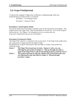
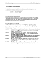
2.16Cooling Module 2 Troubleshooting 2.16 Cooling Module To check if the computer's cooling module is defective or malfunctioning, follow the troubleshooting procedures below as instructed. Procedure 1 Test Program Check Procedure 2 Connector Check and Replacement Check Procedure 1 Test Program Check Execute the Fan On/Off test program available as part of the maintenance test program. This test program checks the cooling module. Insert the diagnostics bootable CD in the computer's CD, turn on the computer and run the test. See Chapter 3 for information on how to perform the test. If any error is detected by the test, go to Procedure 2. Procedure 2 Connector Check and Replacement Check The cooling module is connected to the system board. If the cooling module malfunctions, there may be a bad connection between the cooling module and the system board or either might be faulty. Disassemble the computer following the steps described in Chapter 4 and perform the following checks: Check 1 Make sure the cooling module has been firmly connected to the connector on the system board. Also make sure that the tape is not stuck to any part of the fan and that the fan is free of fore ign matter. Cooling module System board CPU Check 2 Check 3 Check 4 If the connector is disconnected, connect it firmly to the system board and return to Procedure 1. If the tape is stuck to any part of the fan, stick it back to the specified point. If a foreign matter is found in the fan, remove it and then return to Procedure 1. If there is still an error, perform Check 2. The cooling module may be faulty. Replace it with a new one following the steps in Chapter 4. If the cooling module is still not functioning properly, perform Check 3. The memory may be defective. Replace the memory module with a new one following the steps described in Chapter 4. If the problem persist, perform Check 4. The CPU may be faulty. Disassemble the computer following the steps described in Chapter 4 and replace the CPU with a new one. Satellite A100/A105 / TECRA A7 Maintenance Manual 2-29
-
 1
1 -
2
-
3
-
4
-
5
-
6
-
7
-
8
-
9
-
10
-
11
-
12
-
13
-
14
-
15
-
16
-
17
-
18
-
19
-
20
-
21
-
22
-
23
-
24
-
25
-
26
-
27
-
28
-
29
-
30
-
31
-
32
-
33
-
34
-
35
-
36
-
37
-
38
-
39
-
40
-
41
-
42
-
43
-
44
-
45
-
46
-
47
-
48
-
49
-
50
-
51
-
52
-
53
-
54
-
55
-
56
-
57
-
58
-
59
-
60
-
61
-
62
-
63
-
64
-
65
-
66
-
 67
67 -
 68
68 -
 69
69 -
 70
70 -
 71
71 -
 72
72 -
 73
73 -
 74
74 -
 75
75 -
 76
76 -
 77
77 -
78
-
79
-
80
-
81
-
82
-
83
-
84
-
85
-
86
-
87
-
88
-
89
-
90
-
91
-
92
-
93
-
94
-
95
-
96
-
97
-
98
-
99
-
100
-
101
-
102
-
103
-
104
-
105
-
106
-
107
-
108
-
109
-
110
-
111
-
112
-
113
-
114
-
115
-
116
-
117
-
118
-
119
-
120
-
121
-
122
-
123
-
124
-
125
-
126
-
127
-
128
-
129
-
130
-
131
-
132
-
133
-
134
-
135
-
136
-
137
-
138
-
139
-
140
-
141
-
142
-
143
-
144
-
145
-
146
-
147
-
148
-
149
-
150
-
151
-
152
-
153
-
154
-
155
-
156
-
157
-
158
-
159
-
160
-
161
-
162
-
163
-
164
-
165
-
166
-
167
-
168
-
169
-
170
-
171
-
172
-
173
-
174
-
175
-
176
-
177
-
178
-
179
-
180
-
181
-
182
-
183
-
184
-
185
-
186
-
187
-
188
-
189
-
190
-
191
-
192
-
193
-
194
-
195
-
196
-
197
-
198
-
199
-
200
-
201
-
202
-
203
-
204
-
205
-
206
-
207
-
208
-
209
-
210
-
211
-
212
-
213
-
214
-
215
-
216
-
217
-
218
-
219
-
220
-
221
-
222
-
223
-
224
-
225
-
226
-
227
-
228
-
229
-
230
-
231
-
232
-
233
-
234
-
235
-
236
-
237
-
238
-
239
-
240
-
241
-
242
-
243
-
244
-
245
-
246
-
247
-
248
-
249
-
250
-
251
-
252
-
253
-
254
-
255
-
256
-
257
-
258
-
259
-
260
-
261
-
262
-
263
-
264
-
265
-
266
-
267
-
268
-
269
-
270
-
271
-
272
-
273
-
274
-
275
-
276
-
277
-
278
-
279
-
280
-
281
-
282
-
283
-
284
-
285
-
286
-
287
-
288
-
289
-
290
-
291
-
292
-
293
-
294
 |
 |
