Toshiba A105 S4064 Maintenance Manual - Page 186
Disassembling the ODD Drive, 6 ODD Bay Module, Replacement Procedures
 |
UPC - 032017706019
View all Toshiba A105 S4064 manuals
Add to My Manuals
Save this manual to your list of manuals |
Page 186 highlights
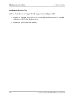
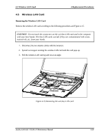
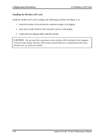
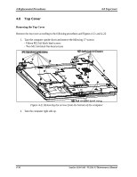
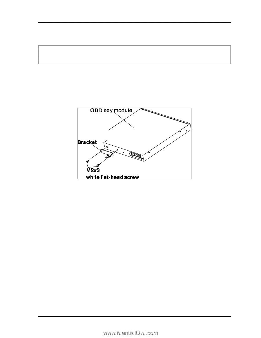
4.6 ODD Bay Module 4 Replacement Procedures Disassembling the ODD Drive NOTE: Do not disassemble the ODD drive when it is working normally. Disassemble or replace the ODD drive only if it fails. Disassemble the ODD drive according to the following procedures and Figure 4-18. 1. Remove two M2x3 white flat-head screws. 2. Remove the bracket. Figure 4-18 Removing the bracket from the ODD drive Assembling the ODD Drive Assemble the ODD drive according to the following procedures and Figure 4-18. 1. Seat the bracket and secure it two M2x3 white flat-head screws. Satellite A100/A105 / TECRA A7 Maintenance Manual 4-33
-
 1
1 -
2
-
3
-
4
-
5
-
6
-
7
-
8
-
9
-
10
-
11
-
12
-
13
-
14
-
15
-
16
-
17
-
18
-
19
-
20
-
21
-
22
-
23
-
24
-
25
-
26
-
27
-
28
-
29
-
30
-
31
-
32
-
33
-
34
-
35
-
36
-
37
-
38
-
39
-
40
-
41
-
42
-
43
-
44
-
45
-
46
-
47
-
48
-
49
-
50
-
51
-
52
-
53
-
54
-
55
-
56
-
57
-
58
-
59
-
60
-
61
-
62
-
63
-
64
-
65
-
66
-
67
-
68
-
69
-
70
-
71
-
72
-
73
-
74
-
75
-
76
-
77
-
78
-
79
-
80
-
81
-
82
-
83
-
84
-
85
-
86
-
87
-
88
-
89
-
90
-
91
-
92
-
93
-
94
-
95
-
96
-
97
-
98
-
99
-
100
-
101
-
102
-
103
-
104
-
105
-
106
-
107
-
108
-
109
-
110
-
111
-
112
-
113
-
114
-
115
-
116
-
117
-
118
-
119
-
120
-
121
-
122
-
123
-
124
-
125
-
126
-
127
-
128
-
129
-
130
-
131
-
132
-
133
-
134
-
135
-
136
-
137
-
138
-
139
-
140
-
141
-
142
-
143
-
144
-
145
-
146
-
147
-
148
-
149
-
150
-
151
-
152
-
153
-
154
-
155
-
156
-
157
-
158
-
159
-
160
-
161
-
162
-
163
-
164
-
165
-
166
-
167
-
168
-
169
-
170
-
171
-
172
-
173
-
174
-
175
-
176
-
177
-
178
-
179
-
180
-
 181
181 -
 182
182 -
 183
183 -
 184
184 -
 185
185 -
 186
186 -
 187
187 -
 188
188 -
 189
189 -
 190
190 -
 191
191 -
192
-
193
-
194
-
195
-
196
-
197
-
198
-
199
-
200
-
201
-
202
-
203
-
204
-
205
-
206
-
207
-
208
-
209
-
210
-
211
-
212
-
213
-
214
-
215
-
216
-
217
-
218
-
219
-
220
-
221
-
222
-
223
-
224
-
225
-
226
-
227
-
228
-
229
-
230
-
231
-
232
-
233
-
234
-
235
-
236
-
237
-
238
-
239
-
240
-
241
-
242
-
243
-
244
-
245
-
246
-
247
-
248
-
249
-
250
-
251
-
252
-
253
-
254
-
255
-
256
-
257
-
258
-
259
-
260
-
261
-
262
-
263
-
264
-
265
-
266
-
267
-
268
-
269
-
270
-
271
-
272
-
273
-
274
-
275
-
276
-
277
-
278
-
279
-
280
-
281
-
282
-
283
-
284
-
285
-
286
-
287
-
288
-
289
-
290
-
291
-
292
-
293
-
294
 |
 |
4.6 ODD Bay Module
4 Replacement Procedures
Satellite A100/A105 / TECRA A7
Maintenance Manual
4-33
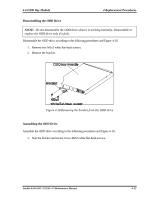
Disassembling the ODD Drive
NOTE:
Do not disassemble the ODD drive when it is working normally. Disassemble or
replace the ODD drive only if it fails.
Disassemble the ODD drive according to the following procedures and Figure 4-18.
1.
Remove two
M2x3 white flat-head screws.
2.
Remove
the
bracket.
Figure 4-18 Removing the bracket from the ODD drive
Assembling the ODD Drive
Assemble the ODD drive according to the following procedures and Figure 4-18.
1.
Seat the bracket and secure it two M2x3 white flat-head screws.