Toshiba A105 S4064 Maintenance Manual - Page 214
Switch Cover and Switch Board, Replacement Procedures
 |
UPC - 032017706019
View all Toshiba A105 S4064 manuals
Add to My Manuals
Save this manual to your list of manuals |
Page 214 highlights
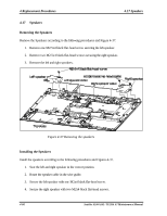
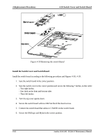
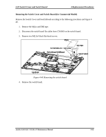
4.18 Switch Cover and Switch board 4 Replacement Procedures 4.18 Switch Cover and Switch Board Removing the Switch Cover and Switch Board (for Consumer Model) Remove the Switch Cover and Switch Board according to the following procedures and Figures 438, 4-39. 1. Remove the Mylar and EMI tape. 2. Disconnect the switch board flat cables from CN4000 on the switch board. 3. Remove two M2.5x4 black flat-head screws. Figure 4-38 Removing the switch cover 4. Turn the top cover right side up. 5. Remove the following 7 latches on the switch cover, in that order: - Two right latches - One latch on the front and bottom sides - Three left latches 6. Remove the switch board. Satellite A100/A105 / TECRA A7 Maintenance Manual 4-61
-
 1
1 -
2
-
3
-
4
-
5
-
6
-
7
-
8
-
9
-
10
-
11
-
12
-
13
-
14
-
15
-
16
-
17
-
18
-
19
-
20
-
21
-
22
-
23
-
24
-
25
-
26
-
27
-
28
-
29
-
30
-
31
-
32
-
33
-
34
-
35
-
36
-
37
-
38
-
39
-
40
-
41
-
42
-
43
-
44
-
45
-
46
-
47
-
48
-
49
-
50
-
51
-
52
-
53
-
54
-
55
-
56
-
57
-
58
-
59
-
60
-
61
-
62
-
63
-
64
-
65
-
66
-
67
-
68
-
69
-
70
-
71
-
72
-
73
-
74
-
75
-
76
-
77
-
78
-
79
-
80
-
81
-
82
-
83
-
84
-
85
-
86
-
87
-
88
-
89
-
90
-
91
-
92
-
93
-
94
-
95
-
96
-
97
-
98
-
99
-
100
-
101
-
102
-
103
-
104
-
105
-
106
-
107
-
108
-
109
-
110
-
111
-
112
-
113
-
114
-
115
-
116
-
117
-
118
-
119
-
120
-
121
-
122
-
123
-
124
-
125
-
126
-
127
-
128
-
129
-
130
-
131
-
132
-
133
-
134
-
135
-
136
-
137
-
138
-
139
-
140
-
141
-
142
-
143
-
144
-
145
-
146
-
147
-
148
-
149
-
150
-
151
-
152
-
153
-
154
-
155
-
156
-
157
-
158
-
159
-
160
-
161
-
162
-
163
-
164
-
165
-
166
-
167
-
168
-
169
-
170
-
171
-
172
-
173
-
174
-
175
-
176
-
177
-
178
-
179
-
180
-
181
-
182
-
183
-
184
-
185
-
186
-
187
-
188
-
189
-
190
-
191
-
192
-
193
-
194
-
195
-
196
-
197
-
198
-
199
-
200
-
201
-
202
-
203
-
204
-
205
-
206
-
207
-
208
-
 209
209 -
 210
210 -
 211
211 -
 212
212 -
 213
213 -
 214
214 -
 215
215 -
 216
216 -
 217
217 -
 218
218 -
 219
219 -
220
-
221
-
222
-
223
-
224
-
225
-
226
-
227
-
228
-
229
-
230
-
231
-
232
-
233
-
234
-
235
-
236
-
237
-
238
-
239
-
240
-
241
-
242
-
243
-
244
-
245
-
246
-
247
-
248
-
249
-
250
-
251
-
252
-
253
-
254
-
255
-
256
-
257
-
258
-
259
-
260
-
261
-
262
-
263
-
264
-
265
-
266
-
267
-
268
-
269
-
270
-
271
-
272
-
273
-
274
-
275
-
276
-
277
-
278
-
279
-
280
-
281
-
282
-
283
-
284
-
285
-
286
-
287
-
288
-
289
-
290
-
291
-
292
-
293
-
294
 |
 |

4.18 Switch Cover and Switch board
4 Replacement Procedures
Satellite A100/A105 / TECRA A7
Maintenance Manual
4
-
61
4.18
Switch Cover and Switch Board
Removing the Switch Cover and Switch Board (for Consumer Model)
Remove the Switch Cover and Switch Board according to the following procedures and Figures 4-
38, 4-39.
1.
Remove the Mylar and EMI tape.
2.
Disconnect the switch board flat cables from CN4000 on the switch board.
3.
Remove two M2.5x4 black flat-head screws.
Figure 4-38 Removing the switch cover
4.
Turn the top cover right side up.
5.
Remove the following 7 latches on the switch cover, in that order:
- Two right latches
- One latch on the front and bottom sides
- Three left latches
6.
Remove the switch board.