Toshiba A105 S4064 Maintenance Manual - Page 160
Colors of Screw Shanks, Symbols of Screws on the Computer Body, Symbol examples
 |
UPC - 032017706019
View all Toshiba A105 S4064 manuals
Add to My Manuals
Save this manual to your list of manuals |
Page 160 highlights
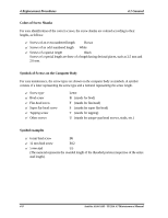
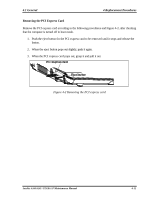
4 Replacement Procedures 4.1 General Colors of Screw Shanks For easy identification of the correct screws, the screw shanks are colored according to their lengths, as follows: ? Screws of an even-numbered length Brown ? Screws of an odd-numbered length White ? Screws of a special length Black Screws of a special length are those of a length having decimal places, such as 2.5 mm and 2.6 mm. Symbols of Screws on the Computer Body For easy maintenance, the screw types are shown on the computer body as symbols. A symbol consists of a letter representing the screw type and a numeral representing the screw length. ? Screw type ? Bind screw ? Flat-head screw ? Super flat-head screw ? Tapping screw ? Other screws Letter B (stands for bind) F (stands for flat-head) S (stands for super flat-head) T (stands for tapping) U (stands for unique-pan head screws, studs, etc.) Symbol examples ? 6 mm bind screw B6 ? 12 mm bind screw B12 ? 5 mm stud U5 (The numeral represents the rounded length of the threaded portion irrespective of the entire stud length.) 4-8 Satellite A100/A105 / TECRA A7 Maintenance Manual
-
 1
1 -
2
-
3
-
4
-
5
-
6
-
7
-
8
-
9
-
10
-
11
-
12
-
13
-
14
-
15
-
16
-
17
-
18
-
19
-
20
-
21
-
22
-
23
-
24
-
25
-
26
-
27
-
28
-
29
-
30
-
31
-
32
-
33
-
34
-
35
-
36
-
37
-
38
-
39
-
40
-
41
-
42
-
43
-
44
-
45
-
46
-
47
-
48
-
49
-
50
-
51
-
52
-
53
-
54
-
55
-
56
-
57
-
58
-
59
-
60
-
61
-
62
-
63
-
64
-
65
-
66
-
67
-
68
-
69
-
70
-
71
-
72
-
73
-
74
-
75
-
76
-
77
-
78
-
79
-
80
-
81
-
82
-
83
-
84
-
85
-
86
-
87
-
88
-
89
-
90
-
91
-
92
-
93
-
94
-
95
-
96
-
97
-
98
-
99
-
100
-
101
-
102
-
103
-
104
-
105
-
106
-
107
-
108
-
109
-
110
-
111
-
112
-
113
-
114
-
115
-
116
-
117
-
118
-
119
-
120
-
121
-
122
-
123
-
124
-
125
-
126
-
127
-
128
-
129
-
130
-
131
-
132
-
133
-
134
-
135
-
136
-
137
-
138
-
139
-
140
-
141
-
142
-
143
-
144
-
145
-
146
-
147
-
148
-
149
-
150
-
151
-
152
-
153
-
154
-
 155
155 -
 156
156 -
 157
157 -
 158
158 -
 159
159 -
 160
160 -
 161
161 -
 162
162 -
 163
163 -
 164
164 -
 165
165 -
166
-
167
-
168
-
169
-
170
-
171
-
172
-
173
-
174
-
175
-
176
-
177
-
178
-
179
-
180
-
181
-
182
-
183
-
184
-
185
-
186
-
187
-
188
-
189
-
190
-
191
-
192
-
193
-
194
-
195
-
196
-
197
-
198
-
199
-
200
-
201
-
202
-
203
-
204
-
205
-
206
-
207
-
208
-
209
-
210
-
211
-
212
-
213
-
214
-
215
-
216
-
217
-
218
-
219
-
220
-
221
-
222
-
223
-
224
-
225
-
226
-
227
-
228
-
229
-
230
-
231
-
232
-
233
-
234
-
235
-
236
-
237
-
238
-
239
-
240
-
241
-
242
-
243
-
244
-
245
-
246
-
247
-
248
-
249
-
250
-
251
-
252
-
253
-
254
-
255
-
256
-
257
-
258
-
259
-
260
-
261
-
262
-
263
-
264
-
265
-
266
-
267
-
268
-
269
-
270
-
271
-
272
-
273
-
274
-
275
-
276
-
277
-
278
-
279
-
280
-
281
-
282
-
283
-
284
-
285
-
286
-
287
-
288
-
289
-
290
-
291
-
292
-
293
-
294
 |
 |