Yamaha 401 Owner's Manual - Page 206
CVP-405: Keyboard Stand Assembly
 |
View all Yamaha 401 manuals
Add to My Manuals
Save this manual to your list of manuals |
Page 206 highlights
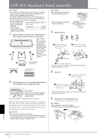
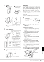
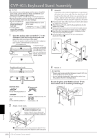
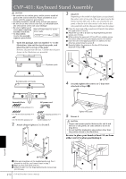
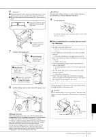
CVP-405: Keyboard Stand Assembly CAUTION • Be careful not to confuse parts, and be sure to install all parts in the correct direction. Please assemble in accor- dance with the sequence given below. • Assembly should be carried out by at least two persons. • Be sure to use the correct screw size, as indicated below. Use of incorrect screws can cause damage. • Be sure to tighten up all screws upon completing assembly of Have a Phillips-head (+) screwdriver ready. each unit. • To disassemble, reverse the assembly sequence given below. 1 Remove all parts from the box. Confirm that all parts shown in the illustration are provided. CAUTION To prevent the A key cover from accidentally opening during assembly, press down on the key cover, mak- ing sure that C D B the sheet (shown) remain in place. CAUTION • Do not place the unit A with the rear side facing down. • Do not lay the unit A upsidedown on the floor. 3 Attach B and C. Incorrect Incorrect B 1 Fix B to the bottom surface of A using two screws. A C 2 Fix B to the speaker box using two screws. A B B E AC power cord Bundled pedal cord inside 5 ✕18 mm fixing screws ✕ 14 3 Fix C in the same way. If the screw holes do not align, loosen the other screws and adjust the position of C and D. 4 Attach D. 2 Fix D to the speaker box using two screws. 2 With the key cover closed and the keyboard side on the bottom, lean A against the wall. CAUTION A Please do not touch the speaker net. Doing so may damage the speaker inside. Be sure to position the keyboard side on the bottom. Spread a large soft cloth, such as a blanket, on the floor. Place the unit A on the cloth with the keyboard side on the bottom and lean A against the wall so that it will not fall or slip. Place a soft cloth against the wall to protect the instrument and wall from scratches. CAUTION • Be careful not to pinch your fingers. • The top part of the music rest is not fixed. When you lean the unit against the wall, support the music rest with your hand so that the music rest will not fall. 1 Fix D to the bottom surface of A using two screws. A D If the screw holes do not align, loosen the other screws and adjust the position of D. 5 Raising A to the standing position. Use the B and C as support to raise A. CAUTION • Be careful not to pinch your fingers. • When you raise A, do not hold the key cover. A Appendix 206 CVP-405/403/401 Owner's Manual
-
 1
1 -
2
-
3
-
4
-
5
-
6
-
7
-
8
-
9
-
10
-
11
-
12
-
13
-
14
-
15
-
16
-
17
-
18
-
19
-
20
-
21
-
22
-
23
-
24
-
25
-
26
-
27
-
28
-
29
-
30
-
31
-
32
-
33
-
34
-
35
-
36
-
37
-
38
-
39
-
40
-
41
-
42
-
43
-
44
-
45
-
46
-
47
-
48
-
49
-
50
-
51
-
52
-
53
-
54
-
55
-
56
-
57
-
58
-
59
-
60
-
61
-
62
-
63
-
64
-
65
-
66
-
67
-
68
-
69
-
70
-
71
-
72
-
73
-
74
-
75
-
76
-
77
-
78
-
79
-
80
-
81
-
82
-
83
-
84
-
85
-
86
-
87
-
88
-
89
-
90
-
91
-
92
-
93
-
94
-
95
-
96
-
97
-
98
-
99
-
100
-
101
-
102
-
103
-
104
-
105
-
106
-
107
-
108
-
109
-
110
-
111
-
112
-
113
-
114
-
115
-
116
-
117
-
118
-
119
-
120
-
121
-
122
-
123
-
124
-
125
-
126
-
127
-
128
-
129
-
130
-
131
-
132
-
133
-
134
-
135
-
136
-
137
-
138
-
139
-
140
-
141
-
142
-
143
-
144
-
145
-
146
-
147
-
148
-
149
-
150
-
151
-
152
-
153
-
154
-
155
-
156
-
157
-
158
-
159
-
160
-
161
-
162
-
163
-
164
-
165
-
166
-
167
-
168
-
169
-
170
-
171
-
172
-
173
-
174
-
175
-
176
-
177
-
178
-
179
-
180
-
181
-
182
-
183
-
184
-
185
-
186
-
187
-
188
-
189
-
190
-
191
-
192
-
193
-
194
-
195
-
196
-
197
-
198
-
199
-
200
-
 201
201 -
 202
202 -
 203
203 -
 204
204 -
 205
205 -
 206
206 -
 207
207 -
 208
208 -
 209
209 -
 210
210 -
 211
211 -
212
-
213
-
214
-
215
-
216
-
217
-
218
-
219
-
220
-
221
-
222
-
223
-
224
-
225
-
226
 |
 |
