2015 Kawasaki KX250F Owners Manual - Page 127
2015 Kawasaki KX250F Manual

Page 127 highlights
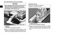
126 MAINTENANCE AND ADJUSTMENT WARNING If the axle holder is not securely clamped, the front fork assembly may come out of the vise when compressed, which could cause an accident resulting in injury. However, clamping the axle holder too tightly can damage it which will affect riding stability. Use protective aluminum covers on the jaws of the vise and do not tighten the vise excessively. the push rod into the piston rod. • Insert the O-ring on the left front fork adjuster • Replace assembly with a new one and apply specified fork A. Left Front Fork Cylinder Unit B. Left Front Fork Outer Tube C. Top Plug Wrench (Special Tool: 57001-1645) j the left front fork adjuster assembly to the • Install push rod. oil to the O-ring. • Hold the axle holder with a vise. ○Protect the axle holder with a soft jaw or heavy cloth when using a vise. NOTE
-
 1
1 -
2
-
3
-
4
-
5
-
6
-
7
-
8
-
9
-
10
-
11
-
12
-
13
-
14
-
15
-
16
-
17
-
18
-
19
-
20
-
21
-
22
-
23
-
24
-
25
-
26
-
27
-
28
-
29
-
30
-
31
-
32
-
33
-
34
-
35
-
36
-
37
-
38
-
39
-
40
-
41
-
42
-
43
-
44
-
45
-
46
-
47
-
48
-
49
-
50
-
51
-
52
-
53
-
54
-
55
-
56
-
57
-
58
-
59
-
60
-
61
-
62
-
63
-
64
-
65
-
66
-
67
-
68
-
69
-
70
-
71
-
72
-
73
-
74
-
75
-
76
-
77
-
78
-
79
-
80
-
81
-
82
-
83
-
84
-
85
-
86
-
87
-
88
-
89
-
90
-
91
-
92
-
93
-
94
-
95
-
96
-
97
-
98
-
99
-
100
-
101
-
102
-
103
-
104
-
105
-
106
-
107
-
108
-
109
-
110
-
111
-
112
-
113
-
114
-
115
-
116
-
117
-
118
-
119
-
120
-
121
-
 122
122 -
 123
123 -
 124
124 -
 125
125 -
 126
126 -
 127
127 -
 128
128 -
 129
129 -
 130
130 -
 131
131 -
 132
132 -
133
-
134
-
135
-
136
-
137
-
138
-
139
-
140
-
141
-
142
-
143
-
144
-
145
-
146
-
147
-
148
-
149
-
150
-
151
-
152
-
153
-
154
-
155
-
156
-
157
-
158
-
159
-
160
-
161
-
162
-
163
-
164
-
165
-
166
-
167
-
168
-
169
-
170
-
171
-
172
-
173
-
174
-
175
-
176
-
177
-
178
-
179
-
180
-
181
-
182
-
183
-
184
-
185
-
186
-
187
-
188
-
189
-
190
-
191
-
192
-
193
-
194
-
195
-
196
-
197
-
198
-
199
-
200
-
201
-
202
 |
 |
