2015 Kawasaki KX250F Owners Manual - Page 129
2015 Kawasaki KX250F Manual

Page 129 highlights
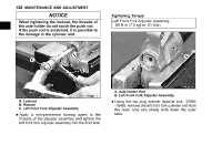
128 MAINTENANCE AND ADJUSTMENT NOTICE When tightening the locknut, the threads of the axle holder do not touch the push rod. If the push rod is scratched, it is possible to the damage in the cylinder unit. j Tightening Torque Left Front Fork Adjuster Assembly: 69 N·m (7.0 kgf·m, 51 ft·lb) A. Axle Holder Part B. Left Front Fork Adjuster Assembly A. Locknut B. Wrench C. Left Front Fork Adjuster Assembly the top plug wrench (special tool: 57001 • Using -1645), remove the left front fork cylinder unit from • Apply a non-permanent locking agent to the threads of the adjuster assembly and tighten the left front fork adjuster assembly into the front fork. the outer tube and slowly slide down the outer tube.
-
 1
1 -
2
-
3
-
4
-
5
-
6
-
7
-
8
-
9
-
10
-
11
-
12
-
13
-
14
-
15
-
16
-
17
-
18
-
19
-
20
-
21
-
22
-
23
-
24
-
25
-
26
-
27
-
28
-
29
-
30
-
31
-
32
-
33
-
34
-
35
-
36
-
37
-
38
-
39
-
40
-
41
-
42
-
43
-
44
-
45
-
46
-
47
-
48
-
49
-
50
-
51
-
52
-
53
-
54
-
55
-
56
-
57
-
58
-
59
-
60
-
61
-
62
-
63
-
64
-
65
-
66
-
67
-
68
-
69
-
70
-
71
-
72
-
73
-
74
-
75
-
76
-
77
-
78
-
79
-
80
-
81
-
82
-
83
-
84
-
85
-
86
-
87
-
88
-
89
-
90
-
91
-
92
-
93
-
94
-
95
-
96
-
97
-
98
-
99
-
100
-
101
-
102
-
103
-
104
-
105
-
106
-
107
-
108
-
109
-
110
-
111
-
112
-
113
-
114
-
115
-
116
-
117
-
118
-
119
-
120
-
121
-
122
-
123
-
 124
124 -
 125
125 -
 126
126 -
 127
127 -
 128
128 -
 129
129 -
 130
130 -
 131
131 -
 132
132 -
 133
133 -
 134
134 -
135
-
136
-
137
-
138
-
139
-
140
-
141
-
142
-
143
-
144
-
145
-
146
-
147
-
148
-
149
-
150
-
151
-
152
-
153
-
154
-
155
-
156
-
157
-
158
-
159
-
160
-
161
-
162
-
163
-
164
-
165
-
166
-
167
-
168
-
169
-
170
-
171
-
172
-
173
-
174
-
175
-
176
-
177
-
178
-
179
-
180
-
181
-
182
-
183
-
184
-
185
-
186
-
187
-
188
-
189
-
190
-
191
-
192
-
193
-
194
-
195
-
196
-
197
-
198
-
199
-
200
-
201
-
202
 |
 |

128
MAINTENANCE AND ADJUSTMENT
j
NOTICE
When tightening the locknut, the threads of
the axle holder do not touch the push rod.
If the push rod is scratched, it is possible to
the damage in the cylinder unit.
A. Locknut
B. Wrench
C. Left Front Fork Adjuster Assembly
•
Apply a non-permanent locking agent to the
threads of the adjuster assembly and tighten the
left front fork adjuster assembly into the front fork.
Tightening Torque
Left Front Fork Adjuster Assembly:
69 N·m (7.0 kgf·m, 51 ft·lb)
A. Axle Holder Part
B. Left Front Fork Adjuster Assembly
•
Using the top plug wrench (special tool: 57001
-1645), remove the left front fork cylinder unit from
the outer tube and slowly slide down the outer
tube.