Adaptec LSM-FC2002 Installation Guide - Page 44
Quad Loop Configuration, Cabling the Quad Loop Configuration
 |
UPC - 760884145067
View all Adaptec LSM-FC2002 manuals
Add to My Manuals
Save this manual to your list of manuals |
Page 44 highlights
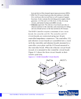
44 Quad Loop Configuration To HBA Note: Quad loop configuration requires that the enclosure be configured in split loop mode. To set split loop mode, a jumper must be installed at jumper location JP3 on each LS module in the enclosure. This section describes the procedure for connecting the enclosure in quad loop mode. For this configuration there must be two LS modules and two I/O modules installed in the enclosure. 1 Remove both LS modules from the enclosure and install a jumper, at jumper location JP3 if one is not already installed. This sets the enclosure to operate in split loop mode. 2 Attach cables to the top and bottom connector of both I/O modules (see Figure 3-4). 3 Attach the other end of these four cables to your host systems. Figure 3-4 Cabling the Quad Loop Configuration To HBA 1 1 2 2 I 0 I 0 To HBA To HBA CAUTION: Enclosures in split loop mode can not be daisy chained to other enclosures. JBOD Configurations
-
 1
1 -
2
-
3
-
4
-
5
-
6
-
7
-
8
-
9
-
10
-
11
-
12
-
13
-
14
-
15
-
16
-
17
-
18
-
19
-
20
-
21
-
22
-
23
-
24
-
25
-
26
-
27
-
28
-
29
-
30
-
31
-
32
-
33
-
34
-
35
-
36
-
37
-
38
-
 39
39 -
 40
40 -
 41
41 -
 42
42 -
 43
43 -
 44
44 -
 45
45 -
 46
46 -
 47
47 -
 48
48 -
 49
49 -
50
-
51
-
52
-
53
-
54
-
55
-
56
-
57
-
58
-
59
-
60
-
61
-
62
-
63
-
64
-
65
-
66
-
67
-
68
-
69
-
70
-
71
-
72
-
73
-
74
-
75
-
76
-
77
-
78
-
79
-
80
-
81
-
82
-
83
-
84
-
85
-
86
-
87
-
88
-
89
-
90
-
91
-
92
-
93
-
94
-
95
-
96
-
97
-
98
-
99
-
100
-
101
-
102
-
103
-
104
-
105
-
106
-
107
-
108
-
109
-
110
 |
 |
