Adaptec LSM-FC2002 Installation Guide - Page 49
RAID Controller Circuit Boards, Board
 |
UPC - 760884145067
View all Adaptec LSM-FC2002 manuals
Add to My Manuals
Save this manual to your list of manuals |
Page 49 highlights
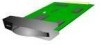
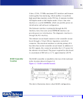
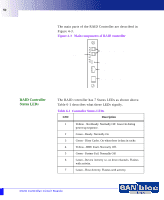
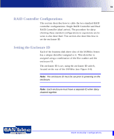
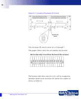
49 Features of the RAID Controller include: • Main processor coupled with a companion chip • Proprietary XOR engine ASIC that provides data processing XOR function and data cache SDRAM control • Four 2Gb-capable fibre protocol chips for the device and host ports • Dual internal 528 MB/s, 64-bit, 66 MHz PCI buses • Separate memory areas for processor and user data • Scalable data cache memory: 128, 256, 512 MB DIMMs • 128 KB NVRAM configuration memory • Real Time Clock • 4 MB Flash PROM • Transparent failover/failback with multiple target ID support The I/O circuit board includes a Battery Backup Unit (BBU) that maintains memory content in case of AC power failure. Power for the BBU is provided by a battery pack mounted in the fan module of the enclosure. RAID Controller Circuit Boards This section gives a brief description of the three RAID controller circuit boards: Controller, I/O, and Ethernet. Controller Circuit Board The controller circuit board oversees and regulates the flow of data from a host through the I/O circuit board to the disk arrays in the 2Gb SANbloc enclosure. The controller circuit board performs these operations with a proprietary archi- tecture, using the following components: • Main microprocessor and companion chip • Control-store memory • Memory Controller/Hardware XOR Engine ASIC (XOR ASIC) • Flash PROM • Non-volatile RAM (NVRAM) • Dual universal asynchronous receiver/transmitter (DUART) • Fibre Channel I/O processors RAID Controller Circuit Boards
-
 1
1 -
2
-
3
-
4
-
5
-
6
-
7
-
8
-
9
-
10
-
11
-
12
-
13
-
14
-
15
-
16
-
17
-
18
-
19
-
20
-
21
-
22
-
23
-
24
-
25
-
26
-
27
-
28
-
29
-
30
-
31
-
32
-
33
-
34
-
35
-
36
-
37
-
38
-
39
-
40
-
41
-
42
-
43
-
 44
44 -
 45
45 -
 46
46 -
 47
47 -
 48
48 -
 49
49 -
 50
50 -
 51
51 -
 52
52 -
 53
53 -
 54
54 -
55
-
56
-
57
-
58
-
59
-
60
-
61
-
62
-
63
-
64
-
65
-
66
-
67
-
68
-
69
-
70
-
71
-
72
-
73
-
74
-
75
-
76
-
77
-
78
-
79
-
80
-
81
-
82
-
83
-
84
-
85
-
86
-
87
-
88
-
89
-
90
-
91
-
92
-
93
-
94
-
95
-
96
-
97
-
98
-
99
-
100
-
101
-
102
-
103
-
104
-
105
-
106
-
107
-
108
-
109
-
110
 |
 |
