Adaptec LSM-FC2002 Installation Guide - Page 54
Location of Enclosure ID Switch, Slot location when viewed from the front of the enclosure
 |
UPC - 760884145067
View all Adaptec LSM-FC2002 manuals
Add to My Manuals
Save this manual to your list of manuals |
Page 54 highlights
54 Figure 4-4 Location of Enclosure ID Switch 1 1 2 2 I 0 I 0 Enclosure ID Switch 1 This enclosure ID switch can be set to 0 through 7. The graphic below shows the slot number and location. Slot location when viewed from the front of the enclosure LSM Slot 0 Slot 1 Slot 2 Slot 3 Slot 4 Slot 5 Slot 6 Slot 7 Slot 8 Slot 9 Slot 10 Slot 11 Slot 12 Slot 13 LSM The fourteen disk drive slots (0 to 13), will be assigned an identifier based on the enclosure ID and the slot number as shown in Table 6-2. Setting the Enclosure ID
-
 1
1 -
2
-
3
-
4
-
5
-
6
-
7
-
8
-
9
-
10
-
11
-
12
-
13
-
14
-
15
-
16
-
17
-
18
-
19
-
20
-
21
-
22
-
23
-
24
-
25
-
26
-
27
-
28
-
29
-
30
-
31
-
32
-
33
-
34
-
35
-
36
-
37
-
38
-
39
-
40
-
41
-
42
-
43
-
44
-
45
-
46
-
47
-
48
-
 49
49 -
 50
50 -
 51
51 -
 52
52 -
 53
53 -
 54
54 -
 55
55 -
 56
56 -
 57
57 -
 58
58 -
 59
59 -
60
-
61
-
62
-
63
-
64
-
65
-
66
-
67
-
68
-
69
-
70
-
71
-
72
-
73
-
74
-
75
-
76
-
77
-
78
-
79
-
80
-
81
-
82
-
83
-
84
-
85
-
86
-
87
-
88
-
89
-
90
-
91
-
92
-
93
-
94
-
95
-
96
-
97
-
98
-
99
-
100
-
101
-
102
-
103
-
104
-
105
-
106
-
107
-
108
-
109
-
110
 |
 |

Setting the Enclosure ID
54
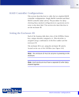
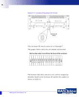
Figure 4-4
Location of Enclosure ID Switch
This enclosure ID switch can be set to 0 through 7.
The graphic below shows the slot number and location.
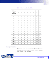
The fourteen disk drive slots (0 to 13), will be assigned an
identifier based on the enclosure ID and the slot number as
shown in Table 6-2.
1
2
1
2
0
I
0
I
Enclosure ID
Switch
1
LSM
LSM
Slot 0
Slot 1
Slot 2
Slot 3
Slot 4
Slot 5
Slot 6
Slot 7
Slot 8
Slot 9
Slot 10
Slot 11
Slot 12
Slot 13
Slot location when viewed from the front of the enclosure