Adaptec LSM-FC2002 Installation Guide - Page 52
RAID Controller Status LEDs, Main components of RAID controller, Table 6-1
 |
UPC - 760884145067
View all Adaptec LSM-FC2002 manuals
Add to My Manuals
Save this manual to your list of manuals |
Page 52 highlights
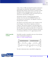
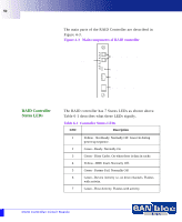
52 The main parts of the RAID Controller are described in Figure 4-3. Figure 4-3 Main components of RAID controller 1 2 3 Status LEDs 4 5 6 7 FC Host Connectors (SSF optical) RS232 HSSDC Connector Ethernet Connection RAID Controller Status LEDs The RAID controller has 7 Status LEDs as shown above. Table 6-1 describes what these LEDs signify. Table 6-1 Controller Status LEDs LED Description 1 Yellow - Not Ready. Normally Off. Goes On during power up sequence. 2 Green - Ready. Normally On 3 Green - Dirty Cache. On when there is data in cache. 4 Yellow - BBU Fault. Normally Off. 5 Green - Partner Fail. Normally Off 6 Green - Device Activity i.e. on drive channels. Flashes with activity. 7 Green - Host Activity. Flashes with activity. RAID Controller Circuit Boards
-
 1
1 -
2
-
3
-
4
-
5
-
6
-
7
-
8
-
9
-
10
-
11
-
12
-
13
-
14
-
15
-
16
-
17
-
18
-
19
-
20
-
21
-
22
-
23
-
24
-
25
-
26
-
27
-
28
-
29
-
30
-
31
-
32
-
33
-
34
-
35
-
36
-
37
-
38
-
39
-
40
-
41
-
42
-
43
-
44
-
45
-
46
-
 47
47 -
 48
48 -
 49
49 -
 50
50 -
 51
51 -
 52
52 -
 53
53 -
 54
54 -
 55
55 -
 56
56 -
 57
57 -
58
-
59
-
60
-
61
-
62
-
63
-
64
-
65
-
66
-
67
-
68
-
69
-
70
-
71
-
72
-
73
-
74
-
75
-
76
-
77
-
78
-
79
-
80
-
81
-
82
-
83
-
84
-
85
-
86
-
87
-
88
-
89
-
90
-
91
-
92
-
93
-
94
-
95
-
96
-
97
-
98
-
99
-
100
-
101
-
102
-
103
-
104
-
105
-
106
-
107
-
108
-
109
-
110
 |
 |
