Adaptec LSM-FC2002 Installation Guide - Page 51
RAID Controller Location,
 |
UPC - 760884145067
View all Adaptec LSM-FC2002 manuals
Add to My Manuals
Save this manual to your list of manuals |
Page 51 highlights
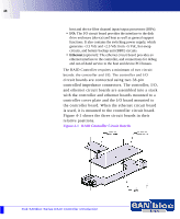
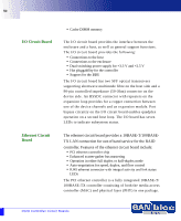
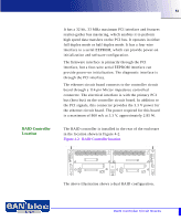
51 RAID Controller Location It has a 32 bit, 33 MHz maximum PCI interface and features scatter-gather bus mastering, which enables it to perform high speed data transfers on the PCI bus. It operates in either full duplex mode or half duplex mode. It has a four wire interface to a serial EEPROM, which can provide power-on initialization and software configuration. The firmware interface is primarily through the PCI interface, but a four-wire serial EEPROM interface can provide power-on initialization. The diagnostic interface is through the PCI interface. The ethernet circuit board connects to the controller circuit board through a 114 pin Mictor impedance controlled connector. The electrical interface is with the primary PCI bus (host bus) on the controller circuit board. In addition to the PCI signals, this connector provides the 3.3 V power for the ethernet circuit board. The power required for this board is a maximum of 860 mA at 3.3 V, approximately 2.85 W. The RAID controller is installed in the rear of the enclosure in the location shown in Figure 4-2. Figure 4-2 RAID Controller location RAID Controller RAID Controller 1 1 1 2 2 1 2 2 3 3 4 4 5 5 6 6 7 7 I 0 I 0 The above illustration shows a dual RAID configuration. RAID Controller Circuit Boards
-
 1
1 -
2
-
3
-
4
-
5
-
6
-
7
-
8
-
9
-
10
-
11
-
12
-
13
-
14
-
15
-
16
-
17
-
18
-
19
-
20
-
21
-
22
-
23
-
24
-
25
-
26
-
27
-
28
-
29
-
30
-
31
-
32
-
33
-
34
-
35
-
36
-
37
-
38
-
39
-
40
-
41
-
42
-
43
-
44
-
45
-
 46
46 -
 47
47 -
 48
48 -
 49
49 -
 50
50 -
 51
51 -
 52
52 -
 53
53 -
 54
54 -
 55
55 -
 56
56 -
57
-
58
-
59
-
60
-
61
-
62
-
63
-
64
-
65
-
66
-
67
-
68
-
69
-
70
-
71
-
72
-
73
-
74
-
75
-
76
-
77
-
78
-
79
-
80
-
81
-
82
-
83
-
84
-
85
-
86
-
87
-
88
-
89
-
90
-
91
-
92
-
93
-
94
-
95
-
96
-
97
-
98
-
99
-
100
-
101
-
102
-
103
-
104
-
105
-
106
-
107
-
108
-
109
-
110
 |
 |
