Asus PU-DLS PU-DLS User Manual - Page 23
compliant host controllers, I/O APIC, SMBus Specification Rev. - chipset
 |
UPC - 610839116966
View all Asus PU-DLS manuals
Add to My Manuals
Save this manual to your list of manuals |
Page 23 highlights
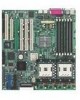
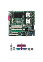
10 IDE connectors. These dual-channel bus master IDE connectors support up to four Ultra DMA/100/66, PIO Modes 3 & 4 IDE devices. Both the primary (blue) and secondary (black) connectors are slotted to prevent incorrect insertion of the IDE ribbon cable. 11 Standby power LED. This LED lights up if there is a standby power on the motherboard, and serves as a reminder to turn off the system power before plugging or unplugging devices. 12 SCSI connector. (See description of item 7.) 13 ASUS ASIC. This chip performs multiple system functions that include hardware and system voltage monitoring, IRQ routing, among others. 14 CPU power fail LED. When lit, this LED (CPULED1) indicates that the CPUs installed on the motherboard are not identical. This LED does not light up if there is only one CPU. 15 LPC super I/O controller. This Low Pin Count (LPC) interface provides the commonly used Super I/O functionality. The chipset supports UART compatible serial ports, one parallel port with EPP and ECP capabilities, a floppy drive, and PS/2 keyboard and mouse. 16 Floppy disk connector. This connector accommodates the provided ribbon cable for the floppy disk drive. One side of the connector is slotted to prevent incorrect insertion of the floppy disk cable. 17 Intel® ICH3-S I/O hub. The I/O Controller Hub 3 (ICH3-S) provides the legacy I/O subsystem and integrates various I/O functions. The ICH3-S provides Hub Interface 1.5 connection to the MCH, dualchannel Ultra ATA/100 bus master IDE controller, integrated LAN controllers, three Universal Host Controller Interface (UHCI) USB 1.1compliant host controllers, I/O APIC, SMBus Specification Rev. 2.0 compliance, Low-Pin Count (LPC) interface, PCI Local Bus Specification Rev. 2.2 compliance. 18 ATI Rage-XL VGA controller. This PCI-based VGA controller supports 8MB display SDRAM for 1280x1024 and true color resolutions. 19 PCI-X/PCI slots. Four 64-bit/100MHz PCI-X slots and two 32-bit/ 33MHz PCI expansion slots support bus master PCI-X/PCI cards. ASUS PU-DLS motherboard user guide 1-9
-
 1
1 -
2
-
3
-
4
-
5
-
6
-
7
-
8
-
9
-
10
-
11
-
12
-
13
-
14
-
15
-
16
-
17
-
 18
18 -
 19
19 -
 20
20 -
 21
21 -
 22
22 -
 23
23 -
 24
24 -
 25
25 -
 26
26 -
 27
27 -
 28
28 -
29
-
30
-
31
-
32
-
33
-
34
-
35
-
36
-
37
-
38
-
39
-
40
-
41
-
42
-
43
-
44
-
45
-
46
-
47
-
48
-
49
-
50
-
51
-
52
-
53
-
54
-
55
-
56
-
57
-
58
-
59
-
60
-
61
-
62
-
63
-
64
-
65
-
66
-
67
-
68
-
69
-
70
-
71
-
72
-
73
-
74
-
75
-
76
-
77
-
78
-
79
-
80
-
81
-
82
-
83
-
84
-
85
-
86
-
87
-
88
-
89
-
90
-
91
-
92
-
93
-
94
-
95
-
96
-
97
-
98
-
99
-
100
-
101
-
102
-
103
-
104
-
105
-
106
-
107
-
108
-
109
-
110
-
111
-
112
-
113
-
114
-
115
-
116
-
117
-
118
-
119
-
120
-
121
-
122
-
123
-
124
-
125
-
126
-
127
-
128
-
129
-
130
-
131
-
132
-
133
-
134
 |
 |
