Asus PU-DLS PU-DLS User Manual - Page 47
SCSI Connection Notes
 |
UPC - 610839116966
View all Asus PU-DLS manuals
Add to My Manuals
Save this manual to your list of manuals |
Page 47 highlights
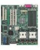
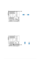
5. Two 68-pin Ultra320 SCSI Connectors (U54, U69) This motherboard has two 68-Pin Ultra320 SCSI connectors; one for each of the two channels. Each channel can support a maximum of 15 devices as specified by Ultra320 standards. ® PU-DLS u69 68-Pin Ultra320 SCSI Connector 1 35 u54 68-Pin Ultra320 SCSI Connector 34 68 PU-DLS Onboard SCSI Connectors 1 35 34 68 SCSI Connection Notes This motherboard has two 68-Pin Ultra320 SCSI connectors; one for each of the two channels. The onboard SCSI chipset incorporates an advanced multi-mode I/O cell that supports both single-ended (SE), Ultra2, Ultra160, and Ultra320 devices. With Ultra320 devices, the SCSI bus platform performs at full Ultra320 speeds (up to 320MB/s) and extended cabling 12m (or 25m in a point-to-point configuration). When an SE device is attached, the bus defaults to an SE speed and 1.5m cable length. Connect SCSI devices as shown. Each channel should have only one type of SCSI standard (e.g. Ultra320, Ultra160, Ultra2, Ultra-Wide). Mixing SCSI devices on the same channel decreases performance of the slower device. ® PU-DLS 68-pin Internal SCSI Cable (Twisted-Pair Ribbon) Channel B Internal SCSI Devices (up to 15 devices) 68-pin Female Terminator 68-pin Internal SCSI Cable (Twisted-Pair Ribbon) Channel A Internal SCSI Devices (up to 15 devices) PU-DLS SCSI Connection Example 68-pin Female Terminator ASUS PU-DLS motherboard user guide 2-21
-
 1
1 -
2
-
3
-
4
-
5
-
6
-
7
-
8
-
9
-
10
-
11
-
12
-
13
-
14
-
15
-
16
-
17
-
18
-
19
-
20
-
21
-
22
-
23
-
24
-
25
-
26
-
27
-
28
-
29
-
30
-
31
-
32
-
33
-
34
-
35
-
36
-
37
-
38
-
39
-
40
-
41
-
 42
42 -
 43
43 -
 44
44 -
 45
45 -
 46
46 -
 47
47 -
 48
48 -
 49
49 -
 50
50 -
 51
51 -
 52
52 -
53
-
54
-
55
-
56
-
57
-
58
-
59
-
60
-
61
-
62
-
63
-
64
-
65
-
66
-
67
-
68
-
69
-
70
-
71
-
72
-
73
-
74
-
75
-
76
-
77
-
78
-
79
-
80
-
81
-
82
-
83
-
84
-
85
-
86
-
87
-
88
-
89
-
90
-
91
-
92
-
93
-
94
-
95
-
96
-
97
-
98
-
99
-
100
-
101
-
102
-
103
-
104
-
105
-
106
-
107
-
108
-
109
-
110
-
111
-
112
-
113
-
114
-
115
-
116
-
117
-
118
-
119
-
120
-
121
-
122
-
123
-
124
-
125
-
126
-
127
-
128
-
129
-
130
-
131
-
132
-
133
-
134
 |
 |
