Asus PU-DLS PU-DLS User Manual - Page 46
Hardware information, SSI/ATX power connectors 24/20-pin U21, 8/4-pin U58
 |
UPC - 610839116966
View all Asus PU-DLS manuals
Add to My Manuals
Save this manual to your list of manuals |
Page 46 highlights
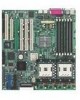
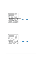
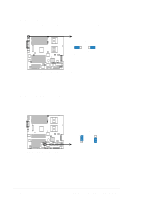
4. SSI/ATX power connectors (24/20-pin U21, 8/4-pin U58) These connectors connect to an SSI/ATX power supply. The plugs from the power supply are designed to fit these connectors in only one orientation. Find the proper orientation and push down firmly until the connectors completely fit. In addition to the 24/20-pin SSI/ATXPWR connector (U21), this motherboard requires that you connect the 8/4-pin SSI12V/ATX12V (U58) power plug to provide sufficient power to the CPU. Make sure that your ATX 12V power supply can provide 8A on the +12V lead and at least 1A on the +5-volt standby lead (+5VSB). The minimum recommended wattage is 230W, or 300W for a fully configured system. The system may become unstable and may experience difficulty powering up if the power supply is inadequate. If you do not connect the 8/4-pin SSI/ATX12V power connector, the system cannot boot up. U21 (SSI/ATXPWR) 24/20-pin Power Connector For Power Supply with 20-pin Power Connector 1 +3 Volts +3 Volts Ground +5 Volts Ground +5 Volts Ground Power OK +5V Standby +12 Volts +12 Volts +3 Volts +3 Volts -12 Volts Ground PSON# Ground Ground Ground -5 Volts +5 Volts +5 Volts +5 Volts Ground ® PU-DLS GND GND GND For Power Supply with 4-pin Power Connector PU-DLS SSI/ATX Power Connector U58 (SSI12V/ATX12V) CPU Power Connector GND 12V 12V 12V 12V 2-20 Chapter 2: Hardware information
-
 1
1 -
2
-
3
-
4
-
5
-
6
-
7
-
8
-
9
-
10
-
11
-
12
-
13
-
14
-
15
-
16
-
17
-
18
-
19
-
20
-
21
-
22
-
23
-
24
-
25
-
26
-
27
-
28
-
29
-
30
-
31
-
32
-
33
-
34
-
35
-
36
-
37
-
38
-
39
-
40
-
 41
41 -
 42
42 -
 43
43 -
 44
44 -
 45
45 -
 46
46 -
 47
47 -
 48
48 -
 49
49 -
 50
50 -
 51
51 -
52
-
53
-
54
-
55
-
56
-
57
-
58
-
59
-
60
-
61
-
62
-
63
-
64
-
65
-
66
-
67
-
68
-
69
-
70
-
71
-
72
-
73
-
74
-
75
-
76
-
77
-
78
-
79
-
80
-
81
-
82
-
83
-
84
-
85
-
86
-
87
-
88
-
89
-
90
-
91
-
92
-
93
-
94
-
95
-
96
-
97
-
98
-
99
-
100
-
101
-
102
-
103
-
104
-
105
-
106
-
107
-
108
-
109
-
110
-
111
-
112
-
113
-
114
-
115
-
116
-
117
-
118
-
119
-
120
-
121
-
122
-
123
-
124
-
125
-
126
-
127
-
128
-
129
-
130
-
131
-
132
-
133
-
134
 |
 |
