Brother International BES-963 Instruction Manual - English - Page 179
ERROR E5 to ERROR FF, head PCB may also be faulty.
 |
View all Brother International BES-963 manuals
Add to My Manuals
Save this manual to your list of manuals |
Page 179 highlights
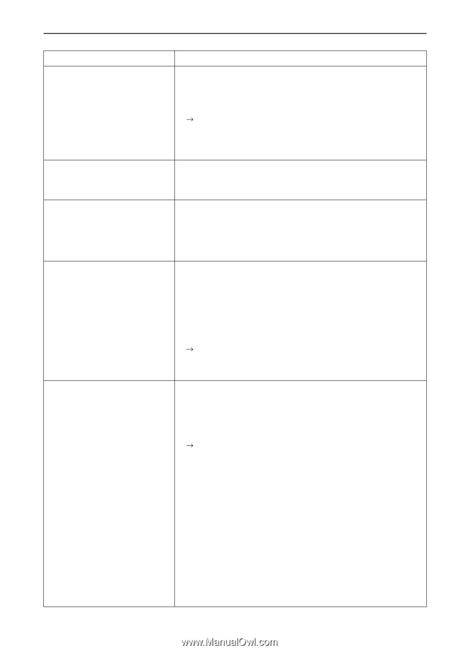
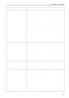
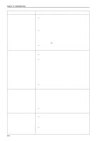
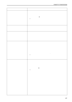
Chapter 10 Troubleshooting Symptom Measures Y-axis motor overcurrent stop occurs. • Measure the resistance values of pin 1 and pin 2, pin 2 and pin 3, pin 3 and pin 4, pin 4 and pin 5, and pin 5 and pin 1 at each connector section of the Y-axis motor with the tester and check to see if they are approximately 2.4Ω. Replace the faulty motor with a new one. • Refer to the block diagram showing the cable connection and check to see if connection from the Y-axis motor to the main PCB is proper. • Replace the main PCB with a new one. The following errors frequently occur. • Replace the main PCB with a new one. • Lower shaft memory error • ERROR E5 to ERROR FF Only a certain head does not operate. • Is the head out of action with either the head switch or the machine controller? • Refer to the block diagram showing cable connections and check to see that other cables are connected to the head switch PCB and the head PCB and the head PCB properly. Jump solenoids and wiper solenoids of all heads do not operate. • Refer to the block diagram showing cable connections and check to see if connection from connector P4 of the power supply PCB in the control box to connector P6 of the power supply PCB in the power supply base, and connection from connector P5 of the power supply PCB in the power supply base to the 39 terminal of the power transformer are proper. • Check fuse F4 on the power supply PCB in the power supply base. If it is blown, replace it with a new one. The 50v circuit is faulty if the fuse is blown immediately after turning on the power even after replacing the fuse. Jump solenoid does not operate. • Check to see if connection from the jump solenoid to connector P10 of the head PCB is proper. • Check the resistance value of the jump solenoid which does not operate with the connector section. The normal resistance value is approximately 56Ω. If it is faulty, replace the solenoid with a new one. In this case, the head PCB may also be faulty. Also replace the head PCB with a new one if it does not operate properly even after replacing the solenoid. • Refer to the block diagram showing the cable connections and check to see if connection from connector P12 of the head PCB to connectors P7, 8, 13, 14, 15, and 16 on the power supply PCB in the control box is proper. • Replace the head PCB with a new one. BES-963BC • BES-1263BC 177
-
 1
1 -
2
-
3
-
4
-
5
-
6
-
7
-
8
-
9
-
10
-
11
-
12
-
13
-
14
-
15
-
16
-
17
-
18
-
19
-
20
-
21
-
22
-
23
-
24
-
25
-
26
-
27
-
28
-
29
-
30
-
31
-
32
-
33
-
34
-
35
-
36
-
37
-
38
-
39
-
40
-
41
-
42
-
43
-
44
-
45
-
46
-
47
-
48
-
49
-
50
-
51
-
52
-
53
-
54
-
55
-
56
-
57
-
58
-
59
-
60
-
61
-
62
-
63
-
64
-
65
-
66
-
67
-
68
-
69
-
70
-
71
-
72
-
73
-
74
-
75
-
76
-
77
-
78
-
79
-
80
-
81
-
82
-
83
-
84
-
85
-
86
-
87
-
88
-
89
-
90
-
91
-
92
-
93
-
94
-
95
-
96
-
97
-
98
-
99
-
100
-
101
-
102
-
103
-
104
-
105
-
106
-
107
-
108
-
109
-
110
-
111
-
112
-
113
-
114
-
115
-
116
-
117
-
118
-
119
-
120
-
121
-
122
-
123
-
124
-
125
-
126
-
127
-
128
-
129
-
130
-
131
-
132
-
133
-
134
-
135
-
136
-
137
-
138
-
139
-
140
-
141
-
142
-
143
-
144
-
145
-
146
-
147
-
148
-
149
-
150
-
151
-
152
-
153
-
154
-
155
-
156
-
157
-
158
-
159
-
160
-
161
-
162
-
163
-
164
-
165
-
166
-
167
-
168
-
169
-
170
-
171
-
172
-
173
-
 174
174 -
 175
175 -
 176
176 -
 177
177 -
 178
178 -
 179
179 -
 180
180 -
 181
181 -
 182
182 -
 183
183 -
 184
184
 |
 |