Brother International BES-963 Instruction Manual - English - Page 21
Names of Machine Components
 |
View all Brother International BES-963 manuals
Add to My Manuals
Save this manual to your list of manuals |
Page 21 highlights
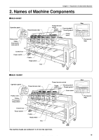
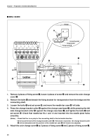
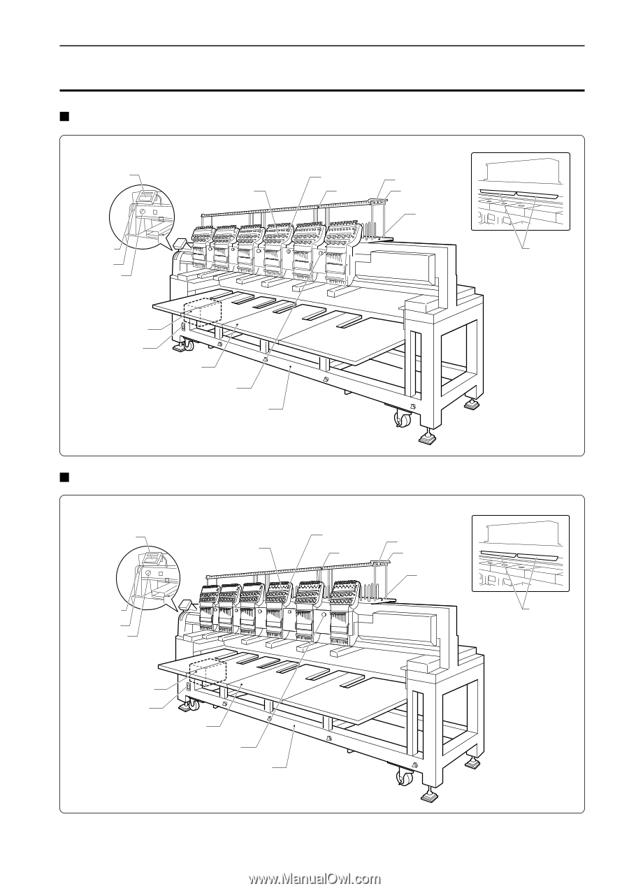
Chapter 1 Preparation of Embroidery Machine 2. Names of Machine Components BES-963BC Operation panel Thread tension dial Pulley cover Pulley Fluorescent lamp switch Thread tension switch Thread guide A Thread guide B Thread guide C Cotton stand Rear Fluorescent lamp Control box Power switch F table Head switch Leg BES-1263BC Operation panel Thread tension dial Pulley cover Pulley Fluorescent lamp switch Control box Power switch F table Head switch Leg Thread tension switch Thread guide A Thread guide B Thread guide C Cotton stand Rear Fluorescent lamp The machine heads are numbered 1 to 6 from the right front. BES-963BC • BES-1263BC 19
-
 1
1 -
2
-
3
-
4
-
5
-
6
-
7
-
8
-
9
-
10
-
11
-
12
-
13
-
14
-
15
-
 16
16 -
 17
17 -
 18
18 -
 19
19 -
 20
20 -
 21
21 -
 22
22 -
 23
23 -
 24
24 -
 25
25 -
 26
26 -
27
-
28
-
29
-
30
-
31
-
32
-
33
-
34
-
35
-
36
-
37
-
38
-
39
-
40
-
41
-
42
-
43
-
44
-
45
-
46
-
47
-
48
-
49
-
50
-
51
-
52
-
53
-
54
-
55
-
56
-
57
-
58
-
59
-
60
-
61
-
62
-
63
-
64
-
65
-
66
-
67
-
68
-
69
-
70
-
71
-
72
-
73
-
74
-
75
-
76
-
77
-
78
-
79
-
80
-
81
-
82
-
83
-
84
-
85
-
86
-
87
-
88
-
89
-
90
-
91
-
92
-
93
-
94
-
95
-
96
-
97
-
98
-
99
-
100
-
101
-
102
-
103
-
104
-
105
-
106
-
107
-
108
-
109
-
110
-
111
-
112
-
113
-
114
-
115
-
116
-
117
-
118
-
119
-
120
-
121
-
122
-
123
-
124
-
125
-
126
-
127
-
128
-
129
-
130
-
131
-
132
-
133
-
134
-
135
-
136
-
137
-
138
-
139
-
140
-
141
-
142
-
143
-
144
-
145
-
146
-
147
-
148
-
149
-
150
-
151
-
152
-
153
-
154
-
155
-
156
-
157
-
158
-
159
-
160
-
161
-
162
-
163
-
164
-
165
-
166
-
167
-
168
-
169
-
170
-
171
-
172
-
173
-
174
-
175
-
176
-
177
-
178
-
179
-
180
-
181
-
182
-
183
-
184
 |
 |
Chapter 1
Preparation of Embroidery Machine
BES-963BC • BES-1263BC
19
Thread tension
switch
Thread guide B
Thread guide C
Thread
guide A
Cotton
stand
F table
Head switch
Leg
Control box
Operation panel
Pulley
Power switch
Thread tension dial
Cotton stand
Thread
guide A
Thread tension switch
Thread guide B
Thread guide C
Thread tension dial
Operation panel
Pulley
Control box
Power switch
Head switch
Leg
Pulley cover
Fluorescent
lamp switch
Rear
Pulley cover
Fluorescent
lamp switch
Rear
Fluorescent
lamp
2. Names of Machine Components
BES-963BC
BES-1263BC
The machine heads are numbered 1 to 6 from the right front.
Fluorescent
lamp
F table