Cisco AS5400XM Installation Guide - Page 31
Getting Help, Where to Go Next - ac
 |
UPC - 746320997261
View all Cisco AS5400XM manuals
Add to My Manuals
Save this manual to your list of manuals |
Page 31 highlights
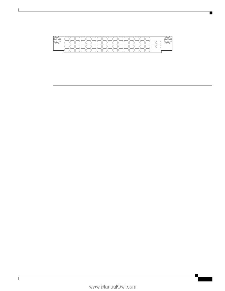
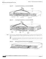
Chapter 2 Feature Card and Carrier Card Guidelines Figure 2-11 Blank Feature Card Cover Getting Help 36033 Step 5 Step 6 For AC-powered units, reconnect the AC power cord. For DC-powered units, remove the tape from the circuit breaker switch handle, and reinstate power by moving the handle of the circuit breaker to the ON position. For more information about the AC and DC power supplies, see the chassis installation guide for your universal gateway. Reconnect all interface cables. Getting Help For information about technical support, onsite service, and exchange and repair services, see the "Obtaining Technical Assistance" section on page xvi. Where to Go Next The remaining chapters of this guide include information about installing and troubleshooting feature cards and about building cables. • Chapter 3, "T1 and E1 Feature Cards" • Chapter 4, "Channelized T3 Feature Card" • Chapter 5, "Universal Port and Dial-Only Feature Cards" • Chapter 6, "Voice Feature Card" • Chapter 7, "Troubleshooting" • Appendix A, "Cabling Specifications" 78-17406-01 Cisco AS5350XM and Cisco AS5400XM Universal Gateways Card Installation Guide 2-7
-
 1
1 -
2
-
3
-
4
-
5
-
6
-
7
-
8
-
9
-
10
-
11
-
12
-
13
-
14
-
15
-
16
-
17
-
18
-
19
-
20
-
21
-
22
-
23
-
24
-
25
-
 26
26 -
 27
27 -
 28
28 -
 29
29 -
 30
30 -
 31
31 -
 32
32 -
 33
33 -
 34
34 -
 35
35 -
 36
36 -
37
-
38
-
39
-
40
-
41
-
42
-
43
-
44
-
45
-
46
-
47
-
48
-
49
-
50
-
51
-
52
-
53
-
54
-
55
-
56
-
57
-
58
-
59
-
60
-
61
-
62
-
63
-
64
-
65
-
66
-
67
-
68
-
69
-
70
-
71
-
72
-
73
-
74
-
75
-
76
-
77
-
78
-
79
-
80
-
81
-
82
-
83
-
84
-
85
-
86
-
87
-
88
-
89
-
90
-
91
-
92
-
93
-
94
-
95
-
96
-
97
-
98
-
99
-
100
-
101
-
102
-
103
-
104
 |
 |