Cisco AS5400XM Installation Guide - Page 90
RJ-45 Pin, Signal, Description, Direction, Twinax Pin, RJ-45 to Twinax Cable Pinouts continued
 |
UPC - 746320997261
View all Cisco AS5400XM manuals
Add to My Manuals
Save this manual to your list of manuals |
Page 90 highlights
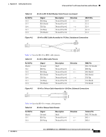
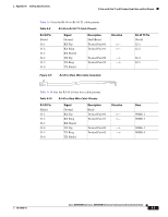
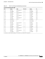
2-Port and 4-Port T1 or E1 Feature Card Cable and Port Pinouts Appendix A Cabling Specifications Table A-6 RJ-45 Pin J1-3 J1-4 J1-5 J1-6 Figure A-4 J1 RJ-45 to Twinax Cable Pinouts (continued) Signal RX Shield TX Tip TX Ring TX Shield Description Twisted Pair #3 Twisted Pair #2 Twisted Pair #2 Twisted Pair #4 Direction -> -> RJ-45-to-RJ-45 Cable Assembly J2 Twinax Pin RX Shield TX-1 TX-2 TX Shield 35645 Table A-7 lists the RJ-45-to-RJ-45 TE cable pinouts. Table A-7 RJ-45-to-RJ-45 TE Cable Pinouts RJ-45 Pin Shield J1-1 J1-2 J1-3 J1-4 J1-5 J1-6 Signal Ground RX Tip RX Ring RX Shield TX Tip TX Ring TX Shield Description Shell/Braid Twisted Pair #1 Twisted Pair #1 Twisted Pair #3 Twisted Pair #2 Twisted Pair #2 Twisted Pair #4 Direction RJ-45 TE Pin Shield J2-1 J2-2 J2-3 J2-4 J2-5 J2-6 Table A-8 lists the RJ-45-to-RJ-45 NT cable pinouts. Table A-8 RJ-45-to-RJ-45 NT Cable Pinouts RJ-45 Pin Shield J1-1 J1-2 J1-3 J1-4 J1-5 J1-6 Signal Ground RX Tip RX Ring RX Shield TX Tip TX Ring TX Shield Description Direction Shell/Braid Twisted Pair #1 Twisted Pair #4 Signal Ground TX Tip TX Ring TX Shield RX Tip RX Ring RX Shield RJ-45 NT Pin Shield J2-4 J2-5 J2-6 J2-1 J2-2 J2-3 Note Because the RJ-45-to-RJ-45 cable has polarity, the pinouts differ depending on which end of the cable you use. Cisco AS5350XM and Cisco AS5400XM Universal Gateways Card Installation Guide A-4 78-17406-01
-
 1
1 -
2
-
3
-
4
-
5
-
6
-
7
-
8
-
9
-
10
-
11
-
12
-
13
-
14
-
15
-
16
-
17
-
18
-
19
-
20
-
21
-
22
-
23
-
24
-
25
-
26
-
27
-
28
-
29
-
30
-
31
-
32
-
33
-
34
-
35
-
36
-
37
-
38
-
39
-
40
-
41
-
42
-
43
-
44
-
45
-
46
-
47
-
48
-
49
-
50
-
51
-
52
-
53
-
54
-
55
-
56
-
57
-
58
-
59
-
60
-
61
-
62
-
63
-
64
-
65
-
66
-
67
-
68
-
69
-
70
-
71
-
72
-
73
-
74
-
75
-
76
-
77
-
78
-
79
-
80
-
81
-
82
-
83
-
84
-
 85
85 -
 86
86 -
 87
87 -
 88
88 -
 89
89 -
 90
90 -
 91
91 -
 92
92 -
 93
93 -
 94
94 -
 95
95 -
96
-
97
-
98
-
99
-
100
-
101
-
102
-
103
-
104
 |
 |
