Cisco AS5400XM Installation Guide - Page 73
Digital Signal Processor Firmware, Getting Help, Where to Go Next
 |
UPC - 746320997261
View all Cisco AS5400XM manuals
Add to My Manuals
Save this manual to your list of manuals |
Page 73 highlights
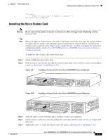
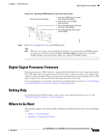
Chapter 6 Voice Feature Card Digital Signal Processor Firmware Figure 6-15 Installing PVDM2 Modules in the Voice Feature Card View from front of board 1. Insert the PVDM2 into the socket at an angle from vertical. 2. Push the top of the PVDM2 down and back. 3. The socket guide posts fit through the holes in the PVDM2. 4. The locking springs clip the back of the PVDM2. 142599 Step 6 Repeat Step 2 through Step 5 for each PVDM2 module. Note When the voice feature card is installed and running, you can check that the PVDM2 modules are installed correctly by entering the show voice dsp summary command. If an installed PVDM2 module is missing from the output, try reseating the PVDM2 module. Digital Signal Processor Firmware Digital signal processor (DSP) firmware is automatically downloaded to the voice feature card from the Cisco IOS image when you boot the system for the first time, or when you insert a voice feature card while the system is operating. When you insert feature cards while the system is operating, the Cisco IOS image recognizes the cards and downloads the required firmware to the cards. For more information on voice feature card firmware and upgrade options, see the Cisco AS5350XM and Cisco AS5400XM Universal Gateways Software Configuration Guide. Getting Help For information about technical support, onsite service, and exchange and repair services, see the "Obtaining Technical Assistance" section on page xvi. Where to Go Next The remaining chapters of this guide include information on troubleshooting feature cards and building cables. • Chapter 7, "Troubleshooting" • Appendix A, "Cabling Specifications" 78-17406-01 Cisco AS5350XM and Cisco AS5400XM Universal Gateways Card Installation Guide 6-11
-
 1
1 -
2
-
3
-
4
-
5
-
6
-
7
-
8
-
9
-
10
-
11
-
12
-
13
-
14
-
15
-
16
-
17
-
18
-
19
-
20
-
21
-
22
-
23
-
24
-
25
-
26
-
27
-
28
-
29
-
30
-
31
-
32
-
33
-
34
-
35
-
36
-
37
-
38
-
39
-
40
-
41
-
42
-
43
-
44
-
45
-
46
-
47
-
48
-
49
-
50
-
51
-
52
-
53
-
54
-
55
-
56
-
57
-
58
-
59
-
60
-
61
-
62
-
63
-
64
-
65
-
66
-
67
-
 68
68 -
 69
69 -
 70
70 -
 71
71 -
 72
72 -
 73
73 -
 74
74 -
 75
75 -
 76
76 -
 77
77 -
 78
78 -
79
-
80
-
81
-
82
-
83
-
84
-
85
-
86
-
87
-
88
-
89
-
90
-
91
-
92
-
93
-
94
-
95
-
96
-
97
-
98
-
99
-
100
-
101
-
102
-
103
-
104
 |
 |
