Cisco AS5400XM Installation Guide - Page 42
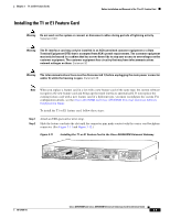
Installing the T1 or E1 Feature Card in the Cisco AS5400XM Universal Gateway
 |
UPC - 746320997261
View all Cisco AS5400XM manuals
Add to My Manuals
Save this manual to your list of manuals |
Page 42 highlights
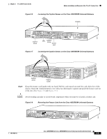
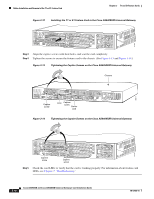
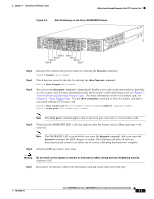
Online Installation and Removal of the T1 or E1 Feature Card Chapter 3 T1 and E1 Feature Cards Figure 3-12 Installing the T1 or E1 Feature Card in the Cisco AS5400XM Universal Gateway 37165 Step 3 Align the captive screws with their holes, and seat the card completely. Step 4 Tighten the screws to secure the feature card to the chassis. (See Figure 3-13 and Figure 3-14.) Figure 3-13 Tightening the Captive Screws on the Cisco AS5350XM Universal Gateway Chassis 0 1 2 PRI Rx Tx ACT OK Captive screw DFC Captive screw Carrier card Figure 3-14 Tightening the Captive Screws on the Cisco AS5400XM Universal Gateway 36817 37163 Captive screw Captive screw Step 5 Check the card LEDs to verify that the card is working properly. For information about feature card LEDs, see Chapter 7, "Troubleshooting." 3-10 Cisco AS5350XM and Cisco AS5400XM Universal Gateways Card Installation Guide 78-17406-01
-
 1
1 -
2
-
3
-
4
-
5
-
6
-
7
-
8
-
9
-
10
-
11
-
12
-
13
-
14
-
15
-
16
-
17
-
18
-
19
-
20
-
21
-
22
-
23
-
24
-
25
-
26
-
27
-
28
-
29
-
30
-
31
-
32
-
33
-
34
-
35
-
36
-
 37
37 -
 38
38 -
 39
39 -
 40
40 -
 41
41 -
 42
42 -
 43
43 -
 44
44 -
 45
45 -
 46
46 -
 47
47 -
48
-
49
-
50
-
51
-
52
-
53
-
54
-
55
-
56
-
57
-
58
-
59
-
60
-
61
-
62
-
63
-
64
-
65
-
66
-
67
-
68
-
69
-
70
-
71
-
72
-
73
-
74
-
75
-
76
-
77
-
78
-
79
-
80
-
81
-
82
-
83
-
84
-
85
-
86
-
87
-
88
-
89
-
90
-
91
-
92
-
93
-
94
-
95
-
96
-
97
-
98
-
99
-
100
-
101
-
102
-
103
-
104
 |
 |
