Cisco AS5400XM Installation Guide - Page 48
Loosening the Captive Screws on the Cisco AS5400XM Universal Gateway
 |
UPC - 746320997261
View all Cisco AS5400XM manuals
Add to My Manuals
Save this manual to your list of manuals |
Page 48 highlights
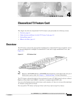
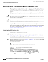
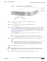
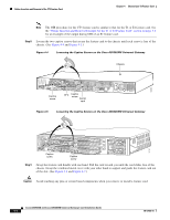
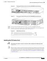
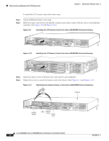
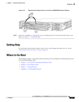
Online Insertion and Removal of the CT3 Feature Card Chapter 4 Channelized T3 Feature Card Note The OIR procedure for the CT3 feature card is similar to that for the T1 or E1 feature card. See the "Online Insertion and Removal Example for the T1 or E1 Feature Card" section on page 3-6 for an example of the output during OIR of an E1 feature card. Step 8 Loosen the two captive screws that secure the feature card to the chassis until each screw is free of the chassis. (See Figure 4-4 and Figure 4-5.) Figure 4-4 Loosening the Captive Screws on the Cisco AS5350XM Universal Gateway Chassis 58760 Captive screw DFC Captive screw Carrier card Figure 4-5 Loosening the Captive Screws on the Cisco AS5400XM Universal Gateway 37167 Step 9 Captive screw Captive screw Grasp the feature card handle with one hand. Pull the card toward you until the card slides free of the chassis. Grasp the ventilated metal cover with your other hand to support and guide the feature card out of the slot. (See Figure 4-6 and Figure 4-7.) Caution Avoid touching any pins or circuit board components when you remove or install a feature card. Cisco AS5350XM and Cisco AS5400XM Universal Gateways Card Installation Guide 4-4 78-17406-01
-
 1
1 -
2
-
3
-
4
-
5
-
6
-
7
-
8
-
9
-
10
-
11
-
12
-
13
-
14
-
15
-
16
-
17
-
18
-
19
-
20
-
21
-
22
-
23
-
24
-
25
-
26
-
27
-
28
-
29
-
30
-
31
-
32
-
33
-
34
-
35
-
36
-
37
-
38
-
39
-
40
-
41
-
42
-
 43
43 -
 44
44 -
 45
45 -
 46
46 -
 47
47 -
 48
48 -
 49
49 -
 50
50 -
 51
51 -
 52
52 -
 53
53 -
54
-
55
-
56
-
57
-
58
-
59
-
60
-
61
-
62
-
63
-
64
-
65
-
66
-
67
-
68
-
69
-
70
-
71
-
72
-
73
-
74
-
75
-
76
-
77
-
78
-
79
-
80
-
81
-
82
-
83
-
84
-
85
-
86
-
87
-
88
-
89
-
90
-
91
-
92
-
93
-
94
-
95
-
96
-
97
-
98
-
99
-
100
-
101
-
102
-
103
-
104
 |
 |
