Cisco VG224 Hardware Installation Guide
Cisco VG224 - Analog Phone Gateway Manual
 |
UPC - 746320575360
View all Cisco VG224 manuals
Add to My Manuals
Save this manual to your list of manuals |
Cisco VG224 manual content summary:
- Cisco VG224 | Hardware Installation Guide - Page 1
Cisco VG224 Voice Gateway Hardware Installation Guide Corporate Headquarters Cisco Systems, Inc. 170 West Tasman Drive San Jose, CA 95134-1706 USA http://www.cisco.com Tel: 408 526-4000 800 553-NETS (6387) Fax: 408 526-4100 Text Part Number: OL-5006-04 - Cisco VG224 | Hardware Installation Guide - Page 2
document or Website are the property of their respective owners. The use of the word partner does not imply a partnership relationship between Cisco and any other company. (0501R) Cisco VG224 Voice Gateway Hardware Installation Guide Copyright © 2003-2005 Cisco Systems, Inc. All rights reserved. - Cisco VG224 | Hardware Installation Guide - Page 3
4 Physical Description and LEDs 5 Chassis Grounding 6 Port Numbering Conventions 6 Specifications 6 Software Elements 7 Configuration Connections 7 Configuration Methods 7 Automated Configuration 7 Manual Configuration 7 OL-5006-04 Cisco VG224 Voice Gateway Hardware Installation Guide 3 - Cisco VG224 | Hardware Installation Guide - Page 4
the Brackets 7 Installing the Cisco VG224 Voice Gateway in a Rack 8 Wall-Mounting the Chassis 9 Bench-Top Installation 11 Installing the Ground Connection 11 Connecting Cables 14 LAN and Power Cables 15 Connecting the Input Power 16 Cable 16 Cisco VG224 Voice Gateway Hardware Installation Guide - Cisco VG224 | Hardware Installation Guide - Page 5
Saving Your Configuration 4 Troubleshooting 4 Cable Specifications and Information 1 Console and Auxiliary Port Cables and Pinouts 1 Identifying a Rollover Cable 2 Console Port to PC 3 Console Port to ASCII Terminal 4 Auxiliary Port to Modem 5 Cisco VG224 Voice Gateway Hardware Installation Guide 5 - Cisco VG224 | Hardware Installation Guide - Page 6
to Terminal and Modem 5 Fast Ethernet Port Pinouts (RJ-45) 6 Analog Voice Multiport Pinouts (RJ-21X/CA21A) 7 EIA/TIA-232 Connections 8 EIA/TIA-449 Connections 8 V.35 Connections 9 X.21 Connections 9 EIA/TIA-530 Connections 9 Cisco VG224 Voice Gateway Hardware Installation Guide 6 OL-5006-04 - Cisco VG224 | Hardware Installation Guide - Page 7
4 Powering On the Powering up the Cisco VG224 voice gateway and preparing for configuration. Cisco VG224 Voice Gateway Appendix A Cable Specifications and Information Pinouts for the Cisco VG224 voice gateway ports and cables. OL-5006-04 Cisco VG224 Voice Gateway Hardware Installation Guide 7 - Cisco VG224 | Hardware Installation Guide - Page 8
in equipment damage or loss of data. Tip Means the following information will help you solve a problem. The tips information might not be troubleshooting or even an action, but could be useful information, similar to a Timesaver. Cisco VG224 Voice Gateway Hardware Installation Guide 8 OL-5006-04 - Cisco VG224 | Hardware Installation Guide - Page 9
that accompanied this device. Statement 1071 Waarschuwing SAVE THESE INSTRUCTIONS BELANGRIJKE VEILIGHEIDSINSTRUCTIES Dit waarschuwingssymbool betekent gevaar. U verkeert in cet appareil. Remarque CONSERVEZ CES INFORMATIONS OL-5006-04 Cisco VG224 Voice Gateway Hardware Installation Guide 9 - Cisco VG224 | Hardware Installation Guide - Page 10
ícese con los procedimientos estándar de prevención de accidentes. Vea las traducciones de las advertencias que acompañan a este dispositivo. Nota GUARDE ESTAS INSTRUCCIONES Cisco VG224 Voice Gateway Hardware Installation Guide 10 OL-5006-04 - Cisco VG224 | Hardware Installation Guide - Page 11
ättningarna av de varningsmeddelanden som finns i denna publikation, och se de översatta säkerhetsvarningarna som medföljer denna anordning. OBS! SPARA DESSA ANVISNINGAR OL-5006-04 Cisco VG224 Voice Gateway Hardware Installation Guide 11 - Cisco VG224 | Hardware Installation Guide - Page 12
åelse af ulykker. Brug erklæringsnummeret efter hver advarsel for at finde oversættelsen i de oversatte advarsler, der fulgte med denne enhed. GEM DISSE ANVISNINGER Cisco VG224 Voice Gateway Hardware Installation Guide 12 OL-5006-04 - Cisco VG224 | Hardware Installation Guide - Page 13
Preface Safety Warnings OL-5006-04 Cisco VG224 Voice Gateway Hardware Installation Guide 13 - Cisco VG224 | Hardware Installation Guide - Page 14
Product Document Title Cisco VG224 voice gateway • Cisco VG224 Voice Gateway Hardware Installation Guide (this book) • Cisco VG224 Voice Gateway Quick Start Guide • Cisco VG224 Voice Gateway Software Configuration Guide Cisco IOS software1 • Cisco VG224 Voice Gateway Regulatory Compliance and - Cisco VG224 | Hardware Installation Guide - Page 15
response card (if present) behind the front cover of your document or by writing to the following address: Cisco Systems Attn: Customer Document Ordering 170 West Tasman Drive San Jose, CA 95134-9883 We appreciate your comments. OL-5006-04 Cisco VG224 Voice Gateway Hardware Installation Guide 15 - Cisco VG224 | Hardware Installation Guide - Page 16
has established severity definitions. Severity 1 (S1)-Your network is "down," or there is a critical impact to your business operations. You and Cisco will commit all necessary resources around the clock to resolve the situation. Cisco VG224 Voice Gateway Hardware Installation Guide 16 OL-5006-04 - Cisco VG224 | Hardware Installation Guide - Page 17
can access the Internet Protocol Journal at this URL: http://www.cisco.com/ipj • World-class networking training is available from Cisco. You can view current offerings at this URL: http://www.cisco.com/en/US/learning/index.html OL-5006-04 Cisco VG224 Voice Gateway Hardware Installation Guide 17 - Cisco VG224 | Hardware Installation Guide - Page 18
Obtaining Additional Publications and Information Preface Cisco VG224 Voice Gateway Hardware Installation Guide 18 OL-5006-04 - Cisco VG224 | Hardware Installation Guide - Page 19
Overview The Cisco VG224 supports the following interfaces: • 10/100BASE-T LAN connection • RJ-21 analog voice interface • External/Internal compact flash The Cisco VG224 can be housed in a rack, mounted on a wall, or set on a bench-top surface. Warning This unit is intended for installation in - Cisco VG224 | Hardware Installation Guide - Page 20
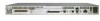
analog voice interface • Two 10/100BASE-T ports • External compact flash memory • AC and DC power inputs Figure 1-2 shows the basic types of Cisco VG224 chassis as seen from the cabling side. Figure 1-2 Cisco VG224 Voice Gateway Chassis VG224-24FXS Product Serial Number Location for the Cisco VG224 - Cisco VG224 | Hardware Installation Guide - Page 21
Chapter 1 Overview of the Cisco VG224 Voice Gateway Figure 1-3 Serial Number Locations Overview AAANNNNXXXX VG224-24FXS AAANNNNXXXX Note The serial number for the Cisco VG224 Voice Gateway is 11 characters long 103055 OL-5006-04 Cisco VG224 Voice Gateway Hardware Installation Guide 1-3 - Cisco VG224 | Hardware Installation Guide - Page 22
services supported by each port type are described in Table 1-2. • Two administrative ports-One console and one auxiliary. • One or two 10/100BASE-T LAN ports. • Cisco VG224 voice gateway for analog voice user interface is equipped with an RJ-21 port for connection to a distribution panel. Cisco - Cisco VG224 | Hardware Installation Guide - Page 23
or 24 analog FXS voice ports ground-start) Port 2/0 to 2/23 CF3 Slot 0 1. DCE = data communications equipment 2. DTE = data terminal equipment 3. CF = compact flash memory LAN Analog phone, fax, or modem Network side of key system Network side of analog PBX Services Supported Details Local - Cisco VG224 | Hardware Installation Guide - Page 24
at 2/0 and extends to 2/7, 2/15, or 2/23, depending on the number of voice ports. Specifications Table 1-3 Cisco VG224 Voice Gateway Technical Specifications Characteristic Dimensions Weight Input power Maximum power surge Input power (DC 12 volt battery) by chassis Value 1.75H x 17.5W x 13 - Cisco VG224 | Hardware Installation Guide - Page 25
downloads the applicable configuration files automatically. Manual Configuration When a Cisco VG224 voice gateway is first installed, use the procedure in Chapter 4, "Power-On Procedure," for the initial configuration. This sets the basic communication parameters. After the Cisco VG224 voice gateway - Cisco VG224 | Hardware Installation Guide - Page 26
Software Elements Chapter 1 Overview of the Cisco VG224 Voice Gateway Cisco VG224 Voice Gateway Hardware Installation Guide 1-8 OL-5006-04 - Cisco VG224 | Hardware Installation Guide - Page 27
ventilated and provide adequate air circulation to ensure proper cooling. The room temperature should be maintained from 32 to 122•F (0 to 50•C). Note The Cisco VG224 voice gateway chassis is designed for front-to-back airflow. OL-5006-04 Cisco VG224 Voice Gateway Hardware Installation Guide 2-1 - Cisco VG224 | Hardware Installation Guide - Page 28
test the airflow by experimenting with different equipment arrangements. Wall-Mounted If the Cisco VG224 voice gateway is installed on a wall, there should be plenty of space on both sides to ensure that there is adequate air flow through the chassis. Bench-Mounted If the unit is placed on a bench - Cisco VG224 | Hardware Installation Guide - Page 29
The VG224 +12V DC power input was designed to be used with an external UPS system, and it has status signals that are reported to the VG224. Table 2-1 shows the connector pin assignment for the +12V DC power connector pin assignment. OL-5006-04 Cisco VG224 Voice Gateway Hardware Installation Guide - Cisco VG224 | Hardware Installation Guide - Page 30
reporting faults on the DC power. If the +12V DC option for powering VG224 is used the AC power must not be used. Figure 2-1 shows the +12V DC power connector. Figure 2-1 +12V DC Power Connector 103121 VG224-24FXS Pin 5 Pin 1 Cisco VG224 Voice Gateway Hardware Installation Guide 2-4 OL-5006-04 - Cisco VG224 | Hardware Installation Guide - Page 31
Your Installation Distance Limitations for Interface Cables Cable Types The cable types that are used are dependent on the Cisco VG224 voice gateway that you are using. For more information, see the "Interfaces and Service Capabilities" section on page 1-4 and Appendix A, "Cable Specifications - Cisco VG224 | Hardware Installation Guide - Page 32
the opening. All module openings must be either occupied or covered to prevent electromagnetic interference. For advice on the prevention of electromagnetic interference, consult experts in radio-frequency interference (RFI). Cisco VG224 Voice Gateway Hardware Installation Guide 2-6 OL-5006-04 - Cisco VG224 | Hardware Installation Guide - Page 33
Only trained and qualified personnel should be allowed to install, replace, or service this equipment. Statement 1030 Warning Read the installation instructions before connecting the system to the power source. Statement 1004 OL-5006-04 Cisco VG224 Voice Gateway Hardware Installation Guide 3-1 - Cisco VG224 | Hardware Installation Guide - Page 34
quickly to turn off the power. • Disconnect all power before installing or removing a chassis. • Do not work alone if potentially hazardous conditions exist. • Never assume that power is disconnected from a circuit. Always check. Cisco VG224 Voice Gateway Hardware Installation Guide 3-2 OL-5006-04 - Cisco VG224 | Hardware Installation Guide - Page 35
expansion history. Update the Site Log to reflect the following: - Configuration changes - Maintenance schedules, requirements, and procedures performed - Comments, notes, and problems - Changes and updates to Cisco IOS software OL-5006-04 Cisco VG224 Voice Gateway Hardware Installation Guide 3-3 - Cisco VG224 | Hardware Installation Guide - Page 36
electrical connections established ASCII terminal attached to console port Modem attached to console port (for remote configuration) Signal distance limits verified Startup sequence steps completed Initial operation verified Cisco VG224 Voice Gateway Hardware Installation Guide 3-4 OL-5006-04 - Cisco VG224 | Hardware Installation Guide - Page 37
Cisco VG224 Voice Gateway Quick Start Guide • Cisco VG224 Voice Gateway Regulatory Compliance and Safety Information Inspect all items for shipping damage. If anything appears damaged, or if you encounter problems when installing or configuring your system, contact a customer service representative - Cisco VG224 | Hardware Installation Guide - Page 38
Chassis Chapter 3 Installing the Cisco VG224 Voice Gateway Rack-Mounting the Chassis Your chassis ships with a pair of brackets for use with a 19-inch rack or mounting on the wall. The bracket is shown in Figure 3-2. Figure 3-2 Quick Mounting Bracket 88815 Mounting Screws Two sets of mounting - Cisco VG224 | Hardware Installation Guide - Page 39
Rack Installation-Rear Panel Forward VG224-24FXS To install the chassis in a center-mount telco rack, attach the brackets as shown in Figure 3-5. Figure 3-5 Telco 19-Inch Rack Installation-Rear Panel Forward VG224-24FXS 95917 OL-5006-04 Cisco VG224 Voice Gateway Hardware Installation Guide 3-7 - Cisco VG224 | Hardware Installation Guide - Page 40
After the brackets are secured to the chassis, you can rack-mount the chassis. Using screws that you provide, attach the chassis to the rack as shown in Figure 3-6 on page 3-8. Figure 3-6 Attaching the Chassis to the 19-Inch Rack VG224 103039 Cisco VG224 Voice Gateway Hardware Installation Guide - Cisco VG224 | Hardware Installation Guide - Page 41
you provide as follows: • You can install a starter screw in the wall, and hook the bracket keyhole over the screw. This holds the unit in place for easy installation of the attachment screws. • Attach both brackets to the wall. OL-5006-04 Cisco VG224 Voice Gateway Hardware Installation Guide 3-9 - Cisco VG224 | Hardware Installation Guide - Page 42
, each bracket requires two wall anchors with washers. Wall anchors and washers must be size #10. • Figure 3-8 shows the orientation required for installation. Figure 3-8 Wall-Mounting the Chassis 1 2 3 4 CISCO IAD2400 103517 3-10 Cisco VG224 Voice Gateway Hardware Installation Guide OL - Cisco VG224 | Hardware Installation Guide - Page 43
Installing the Cisco VG224 Voice Gateway 1 Wall 2 Bracket 3 Wall stud 4 Keyhole for starter screw Bench-Top Installation Bench-Top Installation Step 1 Verify that there is a suitable AC power addition to the power cable ground wire. NEBS Cisco VG224 Voice Gateway Hardware Installation Guide 3-11 - Cisco VG224 | Hardware Installation Guide - Page 44
box and a metal water pipe • Between the Cisco VG224 voice gateway chassis and the ground of a power tap • Between the Cisco VG224 voice gateway chassis and the ground of a junction box A to a grounding point at your site. 3-12 Cisco VG224 Voice Gateway Hardware Installation Guide OL-5006-04 - Cisco VG224 | Hardware Installation Guide - Page 45
the Ground Connection Figure 3-10 NEBS-Compliant Chassis Ground Connection Using Ground Lug Ground lug VG224-24FXS Figure 3-11 Chassis Ground Connection Using Ring Terminal Ring terminal attachment VG224-24FXS 103513 OL-5006-04 Cisco VG224 Voice Gateway Hardware Installation Guide 3-13 - Cisco VG224 | Hardware Installation Guide - Page 46
NEBS Power Cross Tests on FXS Ports NEBS Tests 50 V/0.33 A; 15 minutes 100 V/0.17 A; 15 minutes 200 V/1.00 A; 1-second pulses, 60 repetitions Results Pass Pass Pass Note The installation must comply with all applicable codes. 3-14 Cisco VG224 Voice Gateway Hardware Installation Guide OL-5006 - Cisco VG224 | Hardware Installation Guide - Page 47
Connections 1 3 2 Cisco VG224 4 5 VG224-24FXS 6 Ethernet hub 1 Fast Ethernet port 2 Console port 3 AUX port Modem PC 4 Fast Ethernet (straight-through) 5 RJ-45-to-DB9 console cable 6 RJ-45-to-DB25 auxiliary cable 95920 OL-5006-04 Cisco VG224 Voice Gateway Hardware Installation Guide 3-15 - Cisco VG224 | Hardware Installation Guide - Page 48
Table A-1 on page A-3 and Table A-2 on page A-4 in Appendix A, "Cable Specifications and Information." Step 1 Configure the terminal emulation software requirements: 9600 baud 8 data bits 1 stop bit no parity no flow control 3-16 Cisco VG224 Voice Gateway Hardware Installation Guide OL-5006-04 - Cisco VG224 | Hardware Installation Guide - Page 49
Chapter 3 Installing the Cisco VG224 Voice Gateway Connecting Cables Connecting the Auxiliary Port to a Modem Use the procedure in this section to connect the auxiliary port to a modem. Cable Use an RJ-45-to-DB25 auxiliary cable (labeled Modem). For pinouts, see Table A-3 on page A-5 and Table - Cisco VG224 | Hardware Installation Guide - Page 50
-21 straight-through cable (not included) Figure 3-13 WAN and Voice Connections Distribution panel 1 Cisco VG224 VG224-24FXS 2 Network demarcation 1 RJ-21 cable 2 RJ-45 cable (through a patch panel) to central office 95921 3-18 Cisco VG224 Voice Gateway Hardware Installation Guide OL-5006 - Cisco VG224 | Hardware Installation Guide - Page 51
1 Connect the RJ-21 cable from the analog voice multiport to the distribution panel. Step 2 Secure the cable in place using the strap. Figure 3-14 Analog Voice Connection 103118 VG224-24FXS RJ-21 cable Distribution panel OL-5006-04 Cisco VG224 Voice Gateway Hardware Installation Guide 3-19 - Cisco VG224 | Hardware Installation Guide - Page 52
the remote PC and modem. Set the PC terminal emulation software requirements: 9600 baud 8 data bits 1 stop bit no parity no flow control. Key in and dial the telephone number of the Cisco VG224 voice gateway external modem. 3-20 Cisco VG224 Voice Gateway Hardware Installation Guide OL-5006-04 - Cisco VG224 | Hardware Installation Guide - Page 53
: 9600 baud 8 data bits 1 stop bit no parity no flow control. Key in the telephone number of the Cisco VG224 voice gateway external modem, or, if you are using a Hayes-compatible modem, enter ATDT and the number to be dialed. Connecting Backup Power A Cisco VG224 voice gateway can be installed with - Cisco VG224 | Hardware Installation Guide - Page 54
12V (power) REP_BAT (replace battery) GND (power return) Pin Number 5 6 7 8 Descriptions ON_BAT (battery is on) +12V (power) LOW_BAT (battery is low) GND (power return) Figure 3-16 DC Power Connector VG224-24FXS Pin 5 Pin 1 103121 3-22 Cisco VG224 Voice Gateway Hardware Installation Guide OL - Cisco VG224 | Hardware Installation Guide - Page 55
installation instructions for the UPS. Figure 3-17 shows a setup using a UPS. Note Figure 3-17 shows one possible setup; please review your UPS documents before setting up your system. Figure 3-17 Connecting a UPS to an AC-Powered Cisco VG224 AC wall plug UPS Cisco VG224 voice gateway VG224 - Cisco VG224 | Hardware Installation Guide - Page 56
Connecting Backup Power Chapter 3 Installing the Cisco VG224 Voice Gateway 3-24 Cisco VG224 Voice Gateway Hardware Installation Guide OL-5006-04 - Cisco VG224 | Hardware Installation Guide - Page 57
• Initial Configuration Procedures, page 4-2 • Troubleshooting, page 4-4 Checklist for Power-On You can power on a Cisco VG224 voice gateway if it meets the requirements described in Chapter 3, "Installing the Cisco VG224 Voice Gateway": • The chassis is securely mounted. • Power cable is connected - Cisco VG224 | Hardware Installation Guide - Page 58
Manual Configuration To configure the Cisco VG224 voice gateway from a console (locally or remotely), refer to the Cisco VG224 Voice Gateway Software Configuration Guide for the configuration instructions. To configure it remotely through Telnet, continue to the "Setting the Fast Ethernet Port - Cisco VG224 | Hardware Installation Guide - Page 59
this procedure to set the IP address for the port. After setting this address, you can configure the Cisco VG224 voice gateway remotely through a Telnet connection. Step 1 Step 2 Step 3 Step 4 Command Router# configure terminal Router(config)# enable password password Router(config)# interface - Cisco VG224 | Hardware Installation Guide - Page 60
troubles and solutions. For problems with the configuration, refer to the Cisco VG224 Voice Gateway Software Configuration Guide at the following URL: http://cisco.com/en/US/docs/routers/access/vg224/software/configuration/guide/scg.html Cisco VG224 Voice Gateway Hardware Installation Guide - Cisco VG224 | Hardware Installation Guide - Page 61
Check/replace modem/terminal Check/replace cable Contact Cisco1 or your Cisco reseller Check ventilation Contact Cisco1 or your Cisco reseller Reset/replace console Repeat power-on procedure Contact Cisco1 or your Cisco reseller OL-5006-04 Cisco VG224 Voice Gateway Hardware Installation Guide 4-5 - Cisco VG224 | Hardware Installation Guide - Page 62
Troubleshooting Chapter 4 Powering On the Cisco VG224 Voice Gateway Cisco VG224 Voice Gateway Hardware Installation Guide 4-6 OL-5006-04 - Cisco VG224 | Hardware Installation Guide - Page 63
modem-See Table A-3 and Table A-4 The console port is configured as data communications equipment (DCE); the auxiliary port is configured as data terminal equipment (DTE). Both are asynchronous serial ports and use RJ-45 connectors. OL-5006-04 Cisco VG224 Voice Gateway Hardware Installation Guide - Cisco VG224 | Hardware Installation Guide - Page 64
. (A rollover cable reverses the wire connections at the opposite ends: 1 to 8, 2 to 7, 3 to 6, 4 to 5, 5 to 4, 6 to 3, 7 to 2, and 8 to 1.) Figure A-1 Identifying a Rollover Cable Pin 1 and pin 8 are the same color Pin 1 Pin 8 H11417 Cisco VG224 Voice Gateway Hardware Installation Guide A-2 OL - Cisco VG224 | Hardware Installation Guide - Page 65
3 6 6 2 GND 4 5 5 5 GND 5 4 4 5 RxD 6 3 3 3 DSR 7 2 2 4 CTS 81 1 1 7 1. Pin 1 is connected to pin 8 inside the Cisco VG224 voice gateway. PC Port (DTE, DB-9) Signal CTS DSR RxD GND GND TxD DTR RTS OL-5006-04 Cisco VG224 Voice Gateway Hardware Installation Guide A-3 - Cisco VG224 | Hardware Installation Guide - Page 66
6 3 GND 4 5 5 7 GND 5 4 4 7 RxD 6 3 3 2 DSR 7 2 2 20 CTS 81 1 1 4 1. Pin 1 is connected to pin 8 inside the Cisco VG224 voice gateway. Terminal Port (DTE, DB-25) Signal CTS DSR RxD GND GND TxD DTR RTS Cisco VG224 Voice Gateway Hardware Installation Guide A-4 OL-5006-04 - Cisco VG224 | Hardware Installation Guide - Page 67
DCE, DB-9 female DCE2, DB-25, male DTE2, DB-25, male 1. An octal cable or RJ-45 breakout cable is equivalent to a rollover cable. 2. Modify the DB-25 adapter by removing the wire in pin 6 and placing it in the pin 8 position. OL-5006-04 Cisco VG224 Voice Gateway Hardware Installation Guide A-5 - Cisco VG224 | Hardware Installation Guide - Page 68
Ethernet switch. Figure A-5 RJ-45 Connector Wiring 1 8 H11421 Table A-5 Fast Ethernet Port Pinouts (RJ-45) Pin1 Signal 1 TX+ 2 TX- 3 RX+ 4 - 5 - 6 RX- 7 - 8 - 1. Any pin not referenced is not connected. Cisco VG224 Voice Gateway Hardware Installation Guide A-6 OL-5006-04 - Cisco VG224 | Hardware Installation Guide - Page 69
Ring Tip Ring Tip Ring Tip Ring Tip Ring Tip Ring Tip Ring Tip Ring Tip Ring Tip Ring Tip Ring Tip OL-5006-04 Cisco VG224 Voice Gateway Hardware Installation Guide A-7 - Cisco VG224 | Hardware Installation Guide - Page 70
Port Connector Pin Number Number 24 24 49 - 25, 50, 51, 52 Signal Ring Tip GND EIA/TIA-232 Connections The EIA/TIA-232 standard supports unbalanced circuits at signal speeds up to 64 kbps. For connection to a Cisco VG224 voice gateway serial port, use the EIA/TIA-232 serial transition cable - Cisco VG224 | Hardware Installation Guide - Page 71
Appendix A Cable Specifications and Information Analog Voice Multiport Pinouts (RJ-21X/CA21A) V.35 Connections The V.35 standard is recommended for speeds up to 48 kbps, although in practice it is used successfully at 4 Mbps. The Cisco VG224 voice gateway supports speeds up to 2.048 Mbps. Use the - Cisco VG224 | Hardware Installation Guide - Page 72
Analog Voice Multiport Pinouts (RJ-21X/CA21A) Appendix A Cable Specifications and Information Figure A-11 EIA/TIA-530 Serial Transition Cable Connectors DTE DCE 194831 A-10 Cisco VG224 Voice Gateway Hardware Installation Guide OL-5006-04 - Cisco VG224 | Hardware Installation Guide - Page 73
4 analog voice ports 19, 7 ASCII terminal, connecting 21 auxiliary port 17, 1, 3, 4, 5 B backup battery 21, 23 brackets 6, 9 C cable 5, 1 cable distance limitations 5 cable use reference table 20 caution messages 11 chassis 2 chassis types (illustrated) 2 checklist, installation 4 Cisco IOS software - Cisco VG224 | Hardware Installation Guide - Page 74
rollover cable 2 IN-2 Cisco VG224 Voice Gateway Hardware Installation Guide indicators See LEDs installation 4, 5, 6 installation checklist 4 interface options 1 IOS See Cisco IOS software L lightning, EMI effects 5 log, record keeping 3 M malfunctions, how to diagnose 4 modem 5 modem connections - Cisco VG224 | Hardware Installation Guide - Page 75
16, 20 tools required for installation 5 U uninterruptible power supply 21, 23 V V.35 9 ventilation recommendations 2 voltage selection, AC 3 W wall-mounting the chassis 9, 10 warnings 3 warnings, safety 9, 7, 14 weight, chassis 6 X X.21 9 Cisco VG224 Voice Gateway Hardware Installation Guide IN-3
-
 1
1 -
 2
2 -
 3
3 -
 4
4 -
 5
5 -
 6
6 -
 7
7 -
8
-
9
-
10
-
11
-
12
-
13
-
14
-
15
-
16
-
17
-
18
-
19
-
20
-
21
-
22
-
23
-
24
-
25
-
26
-
27
-
28
-
29
-
30
-
31
-
32
-
33
-
34
-
35
-
36
-
37
-
38
-
39
-
40
-
41
-
42
-
43
-
44
-
45
-
46
-
47
-
48
-
49
-
50
-
51
-
52
-
53
-
54
-
55
-
56
-
57
-
58
-
59
-
60
-
61
-
62
-
63
-
64
-
65
-
66
-
67
-
68
-
69
-
70
-
71
-
72
-
73
-
74
-
75
 |
 |

Corporate Headquarters
Cisco Systems, Inc.
170 West Tasman Drive
San Jose, CA 95134-1706
USA
Tel: 408 526-4000
800 553-NETS (6387)
Fax: 408 526-4100
Cisco VG224 Voice Gateway
Hardware Installation Guide
Text Part Number: OL-5006-04