Cisco VG224 Hardware Installation Guide - Page 30
Direction, Description, SW Register 0x4A80_0038, Definition, V DC Power Connector - power requirements
 |
UPC - 746320575360
View all Cisco VG224 manuals
Add to My Manuals
Save this manual to your list of manuals |
Page 30 highlights
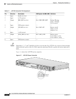
Location and Mounting Requirements Chapter 2 Planning Your Installation Table 2-1 +12V DC Connector Pin Assignment Pin Direction Description 1 Input Enable (tie low) 2 Input +12V (power) 3 Output REP_BAT (tie low) 4 Input GND (power return) 5 Output ON_BAT (tie low) 6 Input +12V (power) 7 Output LOW_BAT (tie low) 8 Input GND (power return) SW Register 0x4A80_0038 Definition - - - - Bit 6: REP_MIS_BAT Battery Missing: Fail 1 = missing Fail 0 = good - - Bit 4: BAT_ON Battery on/off: Status 1 = off Status 0 = on - - Bit 5: BAT_LOW Battery power: Level status 1 = low Level status 0 = okay - - Caution Signal pins 1, 3, 5, and 7 should be tied low to prevent the Cisco VG224 voice gateway from reporting faults on the DC power. If the +12V DC option for powering VG224 is used the AC power must not be used. Figure 2-1 shows the +12V DC power connector. Figure 2-1 +12V DC Power Connector 103121 VG224-24FXS Pin 5 Pin 1 Cisco VG224 Voice Gateway Hardware Installation Guide 2-4 OL-5006-04
-
 1
1 -
2
-
3
-
4
-
5
-
6
-
7
-
8
-
9
-
10
-
11
-
12
-
13
-
14
-
15
-
16
-
17
-
18
-
19
-
20
-
21
-
22
-
23
-
24
-
 25
25 -
 26
26 -
 27
27 -
 28
28 -
 29
29 -
 30
30 -
 31
31 -
 32
32 -
 33
33 -
 34
34 -
 35
35 -
36
-
37
-
38
-
39
-
40
-
41
-
42
-
43
-
44
-
45
-
46
-
47
-
48
-
49
-
50
-
51
-
52
-
53
-
54
-
55
-
56
-
57
-
58
-
59
-
60
-
61
-
62
-
63
-
64
-
65
-
66
-
67
-
68
-
69
-
70
-
71
-
72
-
73
-
74
-
75
 |
 |
