Cisco VG224 Hardware Installation Guide - Page 44
Crimping a Ground Lug onto the Ground Wire, Step 1
 |
UPC - 746320575360
View all Cisco VG224 manuals
Add to My Manuals
Save this manual to your list of manuals |
Page 44 highlights
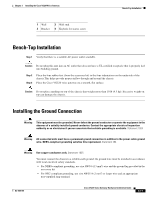
Installing the Ground Connection Chapter 3 Installing the Cisco VG224 Voice Gateway • For EN/IEC 60950-compliant grounding, use size AWG 18 (1 mm2) or larger wire and an appropriate user-supplied ring terminal. To ground the chassis, follow this procedure: Step 1 Locate a suitable ground location. Tip Use a multimeter to measure the resistance between various ground locations, such as the following: • Between the ground of a junction box (outlet) and the ground of a power tap • Between the ground of a junction box and a metal water pipe • Between the Cisco VG224 voice gateway chassis and the ground of a power tap • Between the Cisco VG224 voice gateway chassis and the ground of a junction box A good ground connection should read between 0.0 and 0.5 ohms. Step 2 Step 3 Strip one end of the ground wire to the length required for the ground lug or terminal. • For the NEBS ground lug-approximately 0.75 in. (20 mm) • For user-provided ring terminal-as required Crimp the ground wire to the ground lug or ring terminal, using a crimp tool of the appropriate size. (See Figure 3-9.) Figure 3-9 Crimping a Ground Lug onto the Ground Wire 10360 Step 4 Attach the ground lug or ring terminal to the chassis as shown in Figure 3-10 or Figure 3-11. For the ground lug, use the two screws with captive locking washers provided. For a ring terminal, use one of the screws provided. Use a number 2 Phillips screwdriver, and tighten the screws to a torque of 8 to 10 in-lb (0.9 to 1.1 N-m). Note You can orient the crimped end of the ground lug in either direction (right or left). Step 5 Connect the other end of the ground wire to a grounding point at your site. 3-12 Cisco VG224 Voice Gateway Hardware Installation Guide OL-5006-04
-
 1
1 -
2
-
3
-
4
-
5
-
6
-
7
-
8
-
9
-
10
-
11
-
12
-
13
-
14
-
15
-
16
-
17
-
18
-
19
-
20
-
21
-
22
-
23
-
24
-
25
-
26
-
27
-
28
-
29
-
30
-
31
-
32
-
33
-
34
-
35
-
36
-
37
-
38
-
 39
39 -
 40
40 -
 41
41 -
 42
42 -
 43
43 -
 44
44 -
 45
45 -
 46
46 -
 47
47 -
 48
48 -
 49
49 -
50
-
51
-
52
-
53
-
54
-
55
-
56
-
57
-
58
-
59
-
60
-
61
-
62
-
63
-
64
-
65
-
66
-
67
-
68
-
69
-
70
-
71
-
72
-
73
-
74
-
75
 |
 |