Cisco VG224 Hardware Installation Guide - Page 41
Wall-Mounting the Chassis - off the hook
 |
UPC - 746320575360
View all Cisco VG224 manuals
Add to My Manuals
Save this manual to your list of manuals |
Page 41 highlights
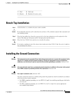
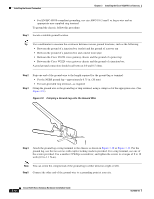
Chapter 3 Installing the Cisco VG224 Voice Gateway Wall-Mounting the Chassis Wall-Mounting the Chassis The following warning applies only when the unit is wall-mounted: Warning This unit is intended to be mounted on a wall. Please read the wall-mounting instructions carefully before beginning installation. Failure to use the correct hardware or to follow the correct procedures could result in a hazardous situation to people and damage to the system. Statement 248 Caution You can wall-mount the unit with either the right or left side facing up; however, the front and rear panels must be vertical. Note For information about obtaining the chassis guard, refer to field notice number 28655, VG224 Chassis Guard - Safety Regulation, at http://www.cisco.com/en/US/ts/fn/200/fn28655.html. To wall-mount the chassis, follow this procedure: Step 1 Attach the short leg of one bracket to the chassis, as shown in Figure 3-7, using two 6-32 x 1/4 slotted hex screws (provided). Be sure to use a plastic washer (provided) with each screw; the narrow end of the washer must fit into the bracket slot, facing the chassis. Caution Be sure to use the correct screws and plastic washers for this mounting option. (See Table 3-1 on page 3-6.) Figure 3-7 Attaching the Brackets for Wall-Mounting 88843 Step 2 Step 3 Attach the second bracket to the opposite side of the chassis. Attach the router to the wall using the brackets previously attached and attachment hardware that you provide as follows: • You can install a starter screw in the wall, and hook the bracket keyhole over the screw. This holds the unit in place for easy installation of the attachment screws. • Attach both brackets to the wall. OL-5006-04 Cisco VG224 Voice Gateway Hardware Installation Guide 3-9
-
 1
1 -
2
-
3
-
4
-
5
-
6
-
7
-
8
-
9
-
10
-
11
-
12
-
13
-
14
-
15
-
16
-
17
-
18
-
19
-
20
-
21
-
22
-
23
-
24
-
25
-
26
-
27
-
28
-
29
-
30
-
31
-
32
-
33
-
34
-
35
-
 36
36 -
 37
37 -
 38
38 -
 39
39 -
 40
40 -
 41
41 -
 42
42 -
 43
43 -
 44
44 -
 45
45 -
 46
46 -
47
-
48
-
49
-
50
-
51
-
52
-
53
-
54
-
55
-
56
-
57
-
58
-
59
-
60
-
61
-
62
-
63
-
64
-
65
-
66
-
67
-
68
-
69
-
70
-
71
-
72
-
73
-
74
-
75
 |
 |