Cisco VG224 Hardware Installation Guide - Page 24
Chassis Grounding, Port Numbering Conventions, Specifications - btu
 |
UPC - 746320575360
View all Cisco VG224 manuals
Add to My Manuals
Save this manual to your list of manuals |
Page 24 highlights
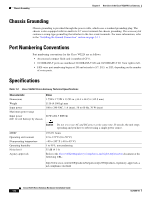
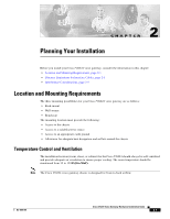
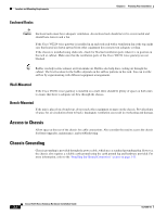
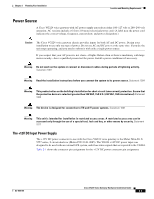
Chassis Grounding Chapter 1 Overview of the Cisco VG224 Voice Gateway Chassis Grounding Chassis grounding is provided through the power cable, which uses a standard grounding plug. The chassis is also equipped with two multi 4 x 0.7 screw terminals for chassis grounding. The accessory kit contains a crimp-type ground lug that attaches to the two screw terminals. For more information, refer to the "Installing the Ground Connection" section on page 3-11. Port Numbering Conventions Port numbering conventions for the Cisco VG224 are as follows: • An external compact flash card is numbered CF 0. • 10/100BASE-T ports are numbered 10/100BASE-T 0/0 and 10/100BASE-T 0/1 from right to left. • FXS voice port numbering begins at 2/0 and extends to 2/7, 2/15, or 2/23, depending on the number of voice ports. Specifications Table 1-3 Cisco VG224 Voice Gateway Technical Specifications Characteristic Dimensions Weight Input power Maximum power surge Input power (DC 12 volt battery) by chassis Value 1.75H x 17.5W x 13.5D in. (44.4 x 444.5 x 342.9 mm) 11 lb (4.106 kg) max 100 to 240 VAC, 1 A (max), 50 to 60 Hz, 70 W (max) 60 W (204.7 BTU/h) MTBF Operating environment Nonoperating temperature Operating humidity Noise level Agency approvals Caution Do not try to use AC and DC power at the same time. If you do, the unit stops operating and you have to reboot using a single power source. 195,671 hours 32 to 122° F (0 to 50° C) -40 to 185° F (-40 to 85° C) 5 to 95%, noncondensing 55 dB @ 3 ft Refer to the Cisco VG224 Regulatory Compliance and Safety Information document at the following URL: http://www.cisco.com/en/US/products/hw/gatecont/ps2250/products_regulatory_approvals_a nd_compliance_list.html Cisco VG224 Voice Gateway Hardware Installation Guide 1-6 OL-5006-04
-
 1
1 -
2
-
3
-
4
-
5
-
6
-
7
-
8
-
9
-
10
-
11
-
12
-
13
-
14
-
15
-
16
-
17
-
18
-
 19
19 -
 20
20 -
 21
21 -
 22
22 -
 23
23 -
 24
24 -
 25
25 -
 26
26 -
 27
27 -
 28
28 -
 29
29 -
30
-
31
-
32
-
33
-
34
-
35
-
36
-
37
-
38
-
39
-
40
-
41
-
42
-
43
-
44
-
45
-
46
-
47
-
48
-
49
-
50
-
51
-
52
-
53
-
54
-
55
-
56
-
57
-
58
-
59
-
60
-
61
-
62
-
63
-
64
-
65
-
66
-
67
-
68
-
69
-
70
-
71
-
72
-
73
-
74
-
75
 |
 |
