Cisco VG224 Hardware Installation Guide - Page 52
Ports, Connectors, and Pinouts, Remote Terminal Connections If Applicable, Connecting to a Modem - fax configuration
 |
UPC - 746320575360
View all Cisco VG224 manuals
Add to My Manuals
Save this manual to your list of manuals |
Page 52 highlights
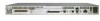
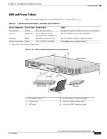
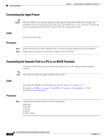
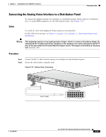
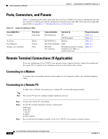
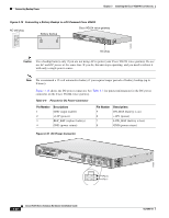
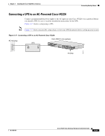
Ports, Connectors, and Pinouts Chapter 3 Installing the Cisco VG224 Voice Gateway Ports, Connectors, and Pinouts Table 3-4 summarizes the cable connections between Cisco VG224 voice gateway and the network and user interfaces. Find the port and the equipment or network type in the table; then look at the applicable pinout table in Appendix A, "Cable Specifications and Information." Table 3-4 Cable Use Reference Table Cisco VG224 Port Console Auxiliary Fast Ethernet Analog voice multiport Port Color Light blue Black Yellow Gray Connector/Cable RJ-45/Rollover RJ-45/Rollover RJ-45/Fast Ethernet RJ-21X/ 50-conductor Interface To PC ASCII terminal Modem LAN Distribution panel for analog telephone, fax, PBX, or central office line Pinout Information Table A-1 Table A-2 Table A-3 Table A-5 Table A-5 Remote Terminal Connections (If Applicable) If you are configuring a Cisco VG224 voice gateway from a remote location, connect the modem and the remote PC or terminal to the telephone network as described in this section. Connecting to a Modem To connect the local modem and the remote modem to live telephone outlets, use standard telephone cables. Connecting to a Remote PC To link a Cisco VG224 voice gateway to a remote PC, use the following procedure: Note The remote PC must be running terminal emulation software. Step 1 Step 2 Step 3 Connect the remote PC and modem. Set the PC terminal emulation software requirements: 9600 baud 8 data bits 1 stop bit no parity no flow control. Key in and dial the telephone number of the Cisco VG224 voice gateway external modem. 3-20 Cisco VG224 Voice Gateway Hardware Installation Guide OL-5006-04
-
 1
1 -
2
-
3
-
4
-
5
-
6
-
7
-
8
-
9
-
10
-
11
-
12
-
13
-
14
-
15
-
16
-
17
-
18
-
19
-
20
-
21
-
22
-
23
-
24
-
25
-
26
-
27
-
28
-
29
-
30
-
31
-
32
-
33
-
34
-
35
-
36
-
37
-
38
-
39
-
40
-
41
-
42
-
43
-
44
-
45
-
46
-
 47
47 -
 48
48 -
 49
49 -
 50
50 -
 51
51 -
 52
52 -
 53
53 -
 54
54 -
 55
55 -
 56
56 -
 57
57 -
58
-
59
-
60
-
61
-
62
-
63
-
64
-
65
-
66
-
67
-
68
-
69
-
70
-
71
-
72
-
73
-
74
-
75
 |
 |