Cisco VG224 Hardware Installation Guide - Page 68
Fast Ethernet Port Pinouts (RJ-45
 |
UPC - 746320575360
View all Cisco VG224 manuals
Add to My Manuals
Save this manual to your list of manuals |
Page 68 highlights
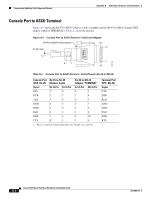
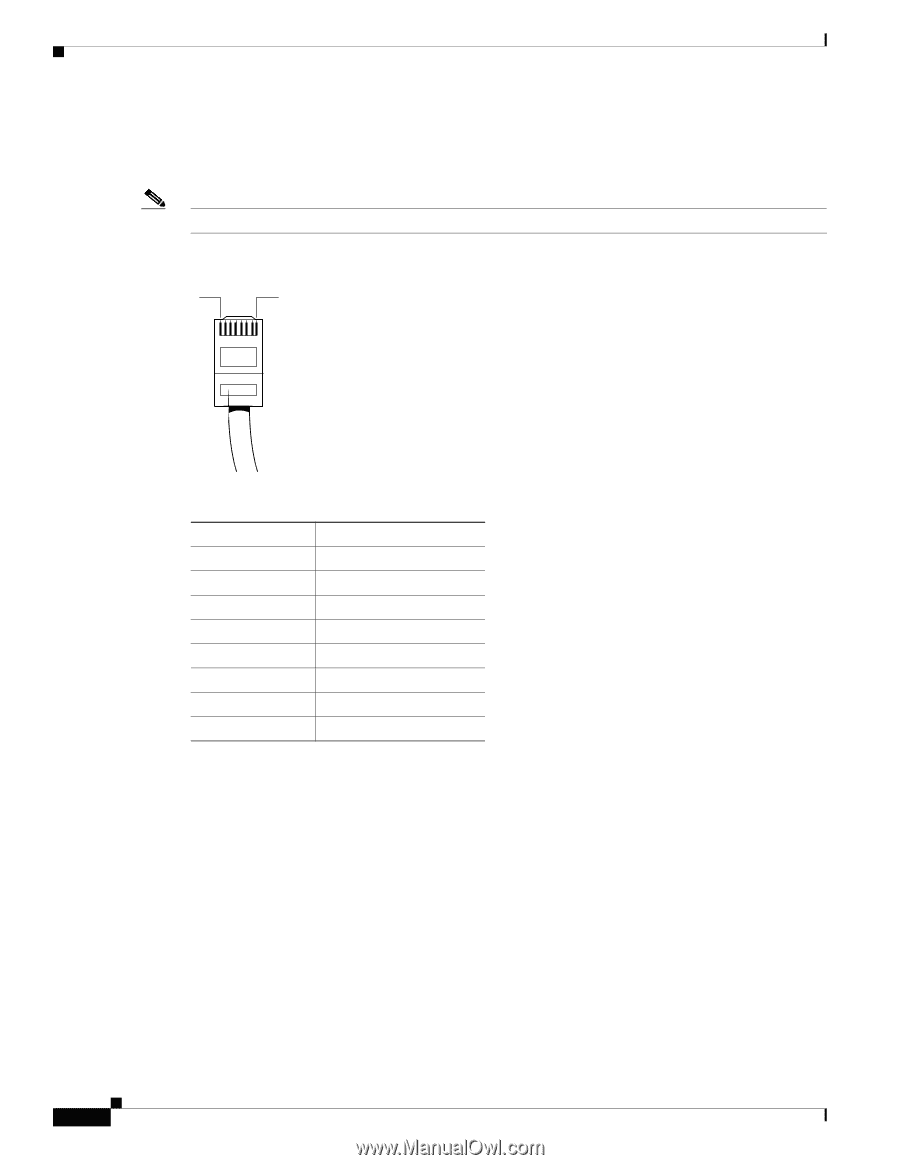
Fast Ethernet Port Pinouts (RJ-45) Appendix A Cable Specifications and Information Fast Ethernet Port Pinouts (RJ-45) Figure A-5 shows the RJ-45 connector wiring for the Fast Ethernet cable; Figure A-5 lists the pinouts. Note Pinout shown is for category 3, 4, or 5 10/100BASE-T connection to an Fast Ethernet switch. Figure A-5 RJ-45 Connector Wiring 1 8 H11421 Table A-5 Fast Ethernet Port Pinouts (RJ-45) Pin1 Signal 1 TX+ 2 TX- 3 RX+ 4 - 5 - 6 RX- 7 - 8 - 1. Any pin not referenced is not connected. Cisco VG224 Voice Gateway Hardware Installation Guide A-6 OL-5006-04
-
 1
1 -
2
-
3
-
4
-
5
-
6
-
7
-
8
-
9
-
10
-
11
-
12
-
13
-
14
-
15
-
16
-
17
-
18
-
19
-
20
-
21
-
22
-
23
-
24
-
25
-
26
-
27
-
28
-
29
-
30
-
31
-
32
-
33
-
34
-
35
-
36
-
37
-
38
-
39
-
40
-
41
-
42
-
43
-
44
-
45
-
46
-
47
-
48
-
49
-
50
-
51
-
52
-
53
-
54
-
55
-
56
-
57
-
58
-
59
-
60
-
61
-
62
-
 63
63 -
 64
64 -
 65
65 -
 66
66 -
 67
67 -
 68
68 -
 69
69 -
 70
70 -
 71
71 -
 72
72 -
 73
73 -
74
-
75
 |
 |
A-6
Cisco VG224 Voice Gateway Hardware Installation Guide
OL-5006-04
Appendix A
Cable Specifications and Information
Fast Ethernet Port Pinouts (RJ-45)
Fast Ethernet Port Pinouts (RJ-45)
Figure A-5
shows the RJ-45 connector wiring for the Fast Ethernet cable;
Figure A-5
lists the pinouts.
Note
Pinout shown is for category 3, 4, or 5 10/100BASE-T connection to an Fast Ethernet switch.
Figure A-5
RJ-45 Connector Wiring
Table A-5
Fast Ethernet Port Pinouts (RJ-45)
Pin
1
1.
Any pin not referenced is not connected.
Signal
1
TX+
2
TX–
3
RX+
4
–
5
–
6
RX–
7
–
8
–
H11421
1
8